Chapter 8
Raster Graphics & Sound
Raster graphics is a term we very rarely use in connection with the Atari computer system. It is a term that describes how individual pixels are mapped on a highresolution screen. The technique is about the only one possible on computers such as the Apple 11 and the IBM PC. Atari programmers like to use easier and more colorful techniques like character graphics and playermissile animation, but there are certainly a number of valid reasons for animating with raster graphics. The two best reasons are that Graphics mode 8 (ANTIC mode F) screens have the highest resolution (320 x 192 pixels), and that very large shapes can be smoothly animated. The biggest disadvantage is that you can have shapes with three colors at best.
Graphics 8 screens produce color by a method known as artifacting. On computers with a GTIA chip, pixels in even columns appear blue and those in odd columns appear green when the background color register is set to black. Obviously, we could obtain other color combinations by varying the background color register. If you wish to draw a shape entirely in blue, you need only plot the shape's individual pixels in the even columns. Similarly, you will obtain an all-green shape if you plot pixels only in the odd columns. When a blue pixel is next to a green pixel, the pair appears as white.
You get these alternating stripes of color because the Atari sends its color signal as a series of square wave pulses. One complete cycle is called a color clock. When the square wave is high you get blue, and when it is low you get green. Other colors are produced by phase shifting the square waves. These colors have nothing to do with the positions of the actual phosphors on the television tube.
Pixel information is encoded eight pixels per byte. The screen is made up of 192 rows of forty bytes. Forty bytes times eight pixels per byte gives a horizontal resolution of 320 pixels. If you are working in color you are really only talking about half that, or 160 pixel pairs horizontally.
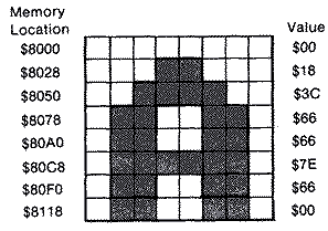
Plotting pixel data is quite anolagous to plotting character data to the screen. In fact, if we took the character data for the letter "A" and plotted it on the screen by calculating the byte address for a particular column in the first eight rows, the character would appear as expected. Of course, it is a lot of trouble to just plot character data on a Graphics 8 screen, but it only illustrates the technique.
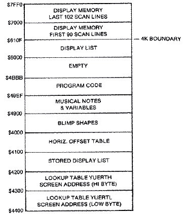
A Graphics 8 screen fortunately can be mapped sequentially in memory if you are clever. The problem is that a display list cannot address screen memory that crosses a 4K boundary. An additional LMS instruction is needed on the other side of the boundary. You could fit 102 lines in the lower portion, but that would leave a 16-byte gap between the two sections. Instead, I decided to place 102 lines in the following example in the top 4K of screen memory and butt the first ninety lines against it in the lower 4K section. This leaves 496 bytes of free memory at the beginning and ample room to place the display list. The display list begins at $6000, and screen memory at $61F0. The 0th or top line starts at that address and the first line begins forty bytes later at $6218. Each of the 192 lines is offset in memory by an additional 40 bytes.
MEMORY ADDRESS = SCREEN MEMORY +(Y*40)+(X/8)
It isn't a difficult calculation, except that in Machine language, multiplication and division other than by multiples of eight require an enormous number of steps. If you only had to do it once, it would be alright. Unfortunately, you need to perform the calculation at least once for each row of the shape. If you were trying to do a Galaxian-type game where you had several dozen shapes, you would never have enough time to move and draw them all and achieve a fast enough animation frame rate. A better method is to look up the starting address of the row from a table and just calculate the horizontal offset based on the shape's Y coordinate.
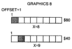
Plotting a pixel on the screen at a particular X,Y coordinate, based on its row and horizontal offset, will work only if the Y coordinate was a multiple of eight. The pixel would be physically at the left end of the byte and would have a value of $FO. If you want to plot a pixel one unit further to the right, you need a byte with an entirely different pixel pattern. You can't physically move the byte just anywhere, like a "tad" to the right. The value of that byte is $80. Now, you begin to realize that you need eight different bytes just to cover all of the possible X coordinates. Since this is also true of larger shapes, we have a difficult problem.
Bit Mapping the Shapes
Drawing a bit-mapped shape table anywhere on the Graphics 8 screen is a simple procedure, once you understand the basic concept. The shape table is stored sequentially in memory, either by rows or columns. The technique, therefore, is to load each of these bytes, one at a time, into the Accumulator, find the position in memory for the screen location where you want to plot that byte, then store it in that location.Memory Location by Table Lookup
The difficulty, as we showed earlier, lies in finding a particular memory location, given an X,Y screen coordinate. Table look-up is obviously the fastest method for finding the starting address for the first position (leftmost) or 0th offset for each of the 192 lines. If the screen started at $61F0, the first line or line #0 would begin at this address, and the second line would begin at $6218. Each address takes two bytes. The first part is the high byte which in the latter case is $62. The second part, $18, is the low byte. These values can be separated into two tables, one containing the lower order address of each line (call it YVERTL), and the other containing the higher order address of each line (call it YVERTH). Each table is 192 bytes long (0-191). In order that these tables not become specific to a particular screen address, the values are merely offset values from a zero starting address. The GETADR subroutine adds the high byte of the starting screen address to obtain a specific memory address. Our only constraint is that the screen start on a page boundary.You can access any element in either table by absolute indexed addressing. The effective address of the operand is computed by adding the contents of the Y register to the address of the instruction. The format is:
EFFECTIVE ADDRESS = ABSOLUTE ADDRESS + Y REGISTER
If our YVERTL table were stored at $4000 and we wanted to find the starting address of line I (remember lines are numbered 0-191), we would index into the table one position and load that value into the Accumulator.
4000:F0 18 40 68 90 B8 ..... YVERTL TABLE
So LDA YVERTL,Y, where the Y register =$01, will fetch the value $18 from memory location $4000 + $01 = $4001, and place it in the Accumulator.
Similarly, if YVERTH were stored in the next page following our first table, then:
4100:01 02 02 02 02 02 ..... YVERTH TABLE
If the Y register = $01, then a LDA YVERTL,Y will take the value $02 stored in memory location $4100 + $01 = $4101, and place it in the Accumulator.
Storing the Shape in Screen Memory
Eventually we will want to store the first byte from the shape table into a memory location. This can be done efficiently if the two-byte address is stored sequentially in zero page. Let's store the low-byte half of the address, HIRESL, at location $F2, and the high-byte half, HIRESH, at location $F3 in zero page:LDY #$01 ;Y REGISTER CONTAINS LINE LDA YVERTH,Y ;LOOKUP HIGH BYTE OF START ;OF ROW IN MEMORY STA HIRESH ;STORE IN ZERO PAGE OF MEMORY LDA YVERTL,Y ;LOOKUP LOW BYE OF ROW IN MEMORY STA HIRESL ;STORE IN ZERO PAGE OF MEMORY
If the computer finds a $00 in location $F2 (HIRESL) and a $60 in location $F3 (HIRESH), then the base address is $6000. The Accumulator stores a value into memory location $60000+$01, or lacation #6001, as shown on the following page.
The final addressing mode that we must consider is Indexed Indirect Addressing. The format is:
LDA (SHPL,X)
It is very similar to the Indirect Indexed addressing mode except the index is added to the zero page base address before it retrieves the effective address. Its primary use is to index a table of effective addresses stored in zero page, but in the form we are going to use it, the X register is set to 0. Thus, it simply finds the base address.
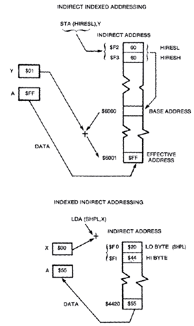
What this all boils down to is that we want to load a byte from a shape table into the Accumulator and store it on the screen with the following instructions:
LDA (SHPL,X) ;LOAD BYTE FROM SHAPE TABLE
STA (HIRESL),Y ;STORE BYTE ON HI-RES SCREEN
We can index into the shape table by incrementing the low byte SHPL by one each time, then store that byte into the next screen position on a particular line by incrementing the Y register. This zero page method is faster than performing the equivalent code with absolute index addressing, because twobyte addresses can be handled with fewer instructions, fewer machine cycles, and less memory space.
Obviously, a generalized subroutine must be developed to find the screen memory address (HIRESL and HIRESH), given a line number and a horizontal displacement. We will call this subroutine GETADR, short for Get Address.
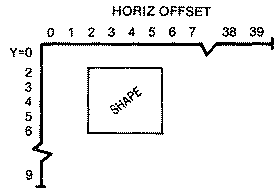
Memory address = Line # starting address + horizontal offset
GETADR	LDA YVERTL,Y	;LOOKUP LOW BYTE ADDRESS OF LINE
	CLC
	ADC HORIZ	;ADD HORIZ. OFFSET
	STA HIRESL	;STORE LOW BYTE OF SCREEN ADDRESS
	LDA YVERTH,Y	;LOOKUP HIGH BYTE ADDRESS OF LINE
	ADC /SCREEN	;ADD HIGH BYTE OF SCREEN ADDRESS
	STA HIRESH	;STORE HIGH BYTE SCREEN ADDRESS
	RTS
where the Y register has a vertical screen value (0-191).
If you are designing an arcade game, you will probably have several different shapes on the screen at one time. Keeping track of each shape's variables, which are inputted into a generalized drawing routine, is generally easier if a set-up routine is incorporated into your program. This assures that you haven't forgotten to initialize anything before entering the drawing routine. Only a few variables need to be defined in the set-up routine: the location of the shape table; the horizontal displacement on the screen; and the width and depth of the shape.
The drawing routine becomes more efficient the fewer times it accesses the GETADR subroutine. Therefore, it is much faster to load and store on the same screen line until the end of the shape's width is reached. Drawing our balloon a byte at a time across its width will only require calling GETADR 31 times. But if we plotted down instead, GETADR would be called for each byte, or 279 times, an unnecessary waste of time.
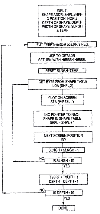
As we load and store across a particular screen line, we decrement SLNGH, the ship's width, until SLNGH equals zero. When we are finished with a row, we increment TVERT to the next screen line down and decrement the DEPTH. When DEPTH reaches zero, we have plotted all rows of the shape and we are finished.
DRAW LDY VERT ;VERTICAL POSITION JSR GETADR ;FIND BEGINNING OF SCREEN ADDRESS ROW LDX #$00 LDA TEMP STA SLNGH ;RESTORE VALUE OF WIDTH FOR NEXT ROW LDY #$00 DRAW2 LDA (SHPL,X) ;GET BYTE OF SHAPE TABLE STA (HIRESL),Y ;PLOT ON SCREEN INC SHPL;NEXT BYTE OF SHAPE TABLE BNE .1
;IF CROSS PAGE BOUNDARY? INC SHPH
;INCREMENT TO NEXT PAGE OF SHAPE .1 INY
;NEXT POSITION ON SCREEN DEC SLNGH ;DECREMENT WIDTH BNE DRAW2 ;FINISHED WITH ROW YET? INC VERT
;IF SO, INCREMENT TO NEXT LINE DEC DEPTH ;DECREMENT DEPTH BNE DRAW
;FINISHED ALL ROWS? RTS
;YES, END
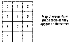
TVERT <= 192-DEPTH
A simple test somewhere before the draw subroutine would suffice, but it might be incorporated into your joystick read routine.
XDrawing Shapes
Objects that move on the screen are shifted in position by erasing the object's first position before drawing it at its new position. The simplest method is to draw the shape by Exclusive-ORing it before shifting it.EOR Instruction
The Exclusive-OR instruction, EOR, is primarily used to determine which bits differ between two operands, but it can also be used to complement selected Accumulator bits. The way it works is elementary. If neither of two particular memory bits is set or their values are zero, the result is zero. If either one is set, then the result is one. But if both are set, they cancel and the result is zero.
       MEMORY BIT    ACCUMULATOR     RESULT BIT IN
                         BIT          ACCUMULATOR
           0              0                0
EOR        0              1                1
           1              0                1
           1              1                0
If we take a byte on the screen and EOR it with the same byte
0 1 1 0 0 1 1 0	    SHAPE ON SCREEN
0 1 1 0 0 1 1 0          SHAPE
_______________
0 0 0 0 0 0 0 0	        RESULT
From the shape table, the result is zero or a screen erase. A similar effect would occur if a blank screen were EORed with a shape, then EORed again.
    0 0 0 0 0 0 0 0    BLANK SCREEN
EOR 0 1 1 0 0 1 1 0    WITH SHAPE
    _______________
    0 1 1 0 0 1 1 0    RESULT IS SHAPE ON SCREEN
EOR 0 1 1 0 0 1 1 0
    _______________
    0 0 0 0 0 0 0 0    RESULT IS BLANK SCREEN
It doesn't damage the background if a shape is EORed on the screen, and then off again. However it does distort the shape slightly.
    0 0 0 0 0 0 0 1    BACKGROUND
EOR 0 0 1 0 1 1 0 0    WITH SHAPE
    _______________
    0 0 1 0 1 1 0 1    RESULT ON SCREEN (SHAPE
                       DISTORTED LAST BIT)
EOR 0 0 1 0 1 1 0 0    WITH SHAPE
    _______________
    0 0 0 0 0 0 0 1    GET BACKGROUND BACK
In the above example, an extra pixel in the shape's last bit position distorts the shape drawn on the screen. In the example below, the fourth bit position becomes a hole in the shape.
    0 0 0 1 0 0 0 0    BACKGROUND
EOR 0 1 0 1 1 0 0 0    WITH SHAPE
    _______________
    0 1 0 0 1 0 0 0    RESULT ON SCREEN
          ^---------hole here
EOR 0 1 0 1 1 0 0 0    WITH SHAPE
    _______________
    0 0 0 1 0 0 0 0
There are some techniques to avoid distorting the shape when the background is likely to interfere during the drawing process. This involves a combination of EORing and ORing the screen with the background stored in an alternate screen memory. An alternate method is to store the screen memory bytes in a temporary table equal in size to your shape, while you draw your shape. When erasing, you replace the shape with the background stored in your temporary table.
OR Instruction
The OR memory with Accumulator (ORA) instruction differs from the EOR instruction in that if both memory and Accumulator bits are on, then the result is one, or on.
       MEMORY BIT    ACCUMULATOR     RESULT BIT IN
                         BIT          ACCUMULATOR
           0              0                0
ORA        0              1                1
           1              0                1
           1              1                1
If the background were as follows, and you ORed it with the shape, the shape remains correct.
    0 0 1 0 1 0 1 0    BACKGROUND
ORA 0 1 1 1 1 0 0 0    WITH SHAPE
    _______________
    0 1 1 1 1 0 1 0    GET SHAPE + BACKGROUND WITH NO HOLE IN SHAPE
Unfortunately, if you EOR this result with the shape again, the background is flawed.
    0 1 1 1 1 0 1 0    SHAPE + BACKGROUND
EOR 0 1 1 1 1 0 0 0    WITH SHAPE
    _______________
    0 0 0 0 0 0 1 0    FLAWED BACKGROUND
We can incorporate the Exclusive-OR instruction in our XDRAW routine. If we EOR the shape we had previously on the screen, nothing remains.
00010 XDRAW	LDY TVERT	;VERTICAL POSITION
00020	JSR GETADR
00030	LDA TEMP
00040	STA SLNGH		;RESTORE VALUE OF WIDTH FOR NEXT ROW
00050	LDX #$00
00060 XDRAW2	LDA (SHPL,X) 	;GET BYTE FROM SHAPE TABLE
00070	EOR (HIRESL),Y	;EOR WITH BYTE ALREADY ON SCREEN
00080	STA (HIRESL),Y	;DRAW ON SCREEN
00090	INC SHPL	;NEXT BYTE OF SHAPE TABLE
00100	INY
00110	DEC SLNGH	;DECREMENT WIDTH
00120	BNE DRAW2	;FINISHED WITH ROW?
00130	INC TVERT	;IF SO, INCREMENT TO NEXT LINE
00140	DEC DEPTH	;DECREMENT DEPTH
00150	BNE DRAW	;FINISHED ALL ROWS?
00160	RTS		;YES, END ROUTINE
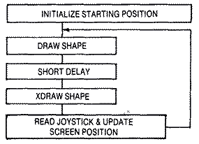
Now that we know how to DRAW and XDRAW a bit-mapped shape anywhere on a Graphics mode 8 screen, the principle for animating them is simple. A shape is erased from the screen, its new position is calculated, then it is redrawn at its new position. The procedure is outlined below.
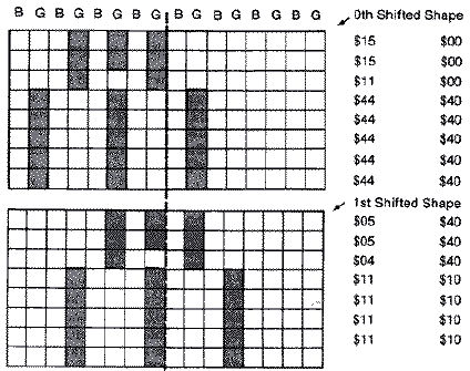
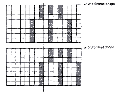
Whenever a shape is moved horizontally, the bit pattern within a screen memory byte shifts and sometimes even intrudes into the adjacent byte. To avoid color shifts due to the odd-even column artifacting, shapes must be moved horizontally two columns at a time. If we consider the four-pixel-wide shape in the diagram below and move it right two bits at a time, it retains the same shape and color pattern, but the value in its shape table changes. If we shift the shape far enough, some of the bits run into the next byte. By the time we have shifted it the fourth time, the pattern repeats itself as if it were in the same starting position but one byte over. So if we are going to be able to move a shape anywhere on the screen, we will need four shifted shape tables each one byte wider than the original shape. And since we need to move the shape horizontally two pixels or color clocks at a time, it would be easier to work with a coordinate system that goes from 0-159 instead of 0-319.
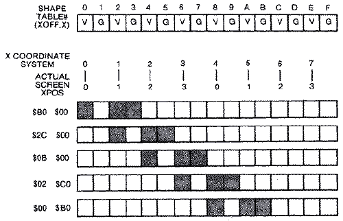
TEMP = INT (X/4)
SHAPE# = X-TEMP*4
Actually, it is a lot faster to look the value up in a table called XOFF. This table has the shape table # for each possible X position. You can retrieve the shape table number by indirectly indexing into the table with the X position in the Y-register. We use another small table SHPLO to store the low byte starting positions of each of the shape tables, and another called SHPHI if the combined length of the four shapes crosses a page boundary. The code to set up the pointers to the proper shape is as follows:
LDY X		;HORIZONTAL POSITION (0-159)
LDX XOFF,Y	;INDEX TO FIND SHAPE #
LDA SHPLO,X	;INDEX TO GET LOW BYTE OF SHAPE TABLE
STA SHPL	;STORE LOW BYTE IN ZERO PAGE
LDA SHPHI,X	;GET HIGH BYTE OF SHAPE TABLE
STA SHPH	;STORE HIGH BYTE IN ZERO PAGE
The drawing routine is exactly the one described earlier. Once the pointers to the proper shape table are inputted with both the shape's vertical position and horizontal offset, bytes can be transferred to screen memory from the appropriate shape table.
The XDRAW subroutine differs from our drawing routine in only one instruction. Instead of just fetching a byte from our shape table and placing it directly in screen memory, this routine EORs it with the byte already on the screen before storing it there. The bits are effectively erased if the screen image byte and the shape table byte are a match.
LDA (SHPL,X)   ;GET BYTE FROM SHAPE TABLE
EOR (HIRESL),Y ;EOR WITH SCREEN IMAGE
STA (HIRESL),Y ;PLOT ON SCREEN
Collision Detection
Detecting collisions between raster shapes isn't easy. There aren't any collision registers to query as you can when working with player-missile shapes. Instead, when drawing the shape, you must simultaneously test for any other pixels within that byte's (or pixel's) screen location. The test is performed using the AND instruction.The AND Instruction
The truth table for the AND instruction is as follows:ACC. MEMORY RESULT 0 0 0 0 1 0 1 0 0 1 1 1Both Accumulator and memory must be on (set) for the result to be on (set).
If we take a screen memory location that has an object in it and AND it with a byte from our shape table, any duplication in any bit location where something is already on the screen will give a non-zero result.
	0 1 1 1 1 0 0 0	   Background
AND	0 0 0 1 1 1 1 1    Shape
	_______________
	0 0 0 1 1 0 0 0	   Result $18 >Zero
Drawing While Testing for Collision
Usually, in any game, if a collision is detected, the object is to be removed. Your first instinct is to stop drawing the object since it is to be removed anyway. But if you are Exclusive-ORing (EORing) the screen and you stop in the middle of your shape, you are going to leave a mess. It is much better to set a collision flag, finish drawing the shape, then remove the object later by completely EORing the shape off the screen.LDA (SHPL,X) ;GET BYTE FROM SHAPE TABLE AND (HIRESL),Y ;AND WITH SCREEN IMAGE BEQ DRAW ;BRANCH ON NO COLLISION LDA #$01 ;SET COLLISION FLAG STA ESET DRAW LDA (SHPL,X) ;GET BYTE FROM SHAPE TABLE EOR (HIRESL),Y ;EOR WITH SCREEN IMAGE STA (HIRESQ,Y ;PLOT ON SCREEN
Collision Detection - A Special Case
Any two objects of byte size or larger should have no problem with collision detection, especially if you are working with solid white objects. But there is a specific case involving artifacting in which collision detection would not work. Let us assume that we have a blue spaceship and a green alien that appear to collide. If ,we examine their bit patterns, you will notice that they never coincide.B G B G B G B G B G B G _______________________ 0 0 1 0 1 0 1 0 1 0 1 0 SHIP AND 0 0 0 1 0 1 0 1 0 1 0 0 ALIEN _______________________ 0 0 0 0 0 0 0 0 0 0 0 0 RESULT OThe solution is to test the ship against screen memory with what is called a "mask" of the ship's shape, as if the ship were solid white. We take this mask of the ship, which has both blue and green pixels lit, and AND it against the alien occupying the same screen locations. A collision will be detected in this case. We set a flag, and then take the appropriate byte from the blue ship's shape table and EOR it against the screen.
Blimp Example
A good raster graphics example would be one that would be difficult or impossible to do with either animated character graphics or player-missile graphics. The large elongated blimp shape in this example is eight bytes wide (nine if you count the byte needed for the offset shapes), and thirty-one scan lines deep. By artifacting, we are able to produce a shape of three different colors: blue, green, and white. The shape is outlined below.The blimp is joys tick-con trolled and therefore free to move anywhere on the screen. You have to be very careful that you don't try to plot the shape beyond the screen boundaries. While plotting bytes beyond the right edge would produce a wraparound effect at the left edge one scan line lower, plotting beyond scan line 191 could create severe problems by wiping out some portion of memory. If we exceed the bounds of our YVERTL, YVERTH tables, unknown pointers to our plotting position in screen memory would be placed in zero page. In this case, the vertical position cannot exceed 192-31 = 161. All of these tests are incorporated in the joystick subroutine.
Flickering Problem with Large Raster Shapes
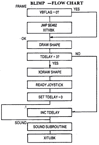
The first time we attempted the example, we placed the raster drawing code outside of VBlank and the music routine in VBlank. Unfortunately, the rastered image flickered badly because the image, after remaining on the screen for several frames, has to be erased at some point before it is redrawn at its new position. Since this takes place when the electron beam is on the screen, there is a slight gap, possibly as long as a frame, before the redrawn image is in place. This never seems to be a problem on other computers like the Apple 11, but then they use interlacing techniques to produce their television images while the Atari does not.We then felt that the animation should become flicker-free if we moved the raster drawing routines inside VBlank. This way the rastered image could be erased and redrawn while the electron beam was mostly off-screen. We arranged the code so that the shape is drawn initially, remains stationary on the screen for three television frames, then is erased, moved, and redrawn on the fourth frame. A timer called TDELAY is set to zero after each erasure, and increments with each frame. A test will cause a branch past the erase-moveredraw code when TDELAY is not equal to three. When it is equal, it will erase the shape, read the joystick, calculate its new position, then redraw it in that position.
We feared that the code might be too long to fit within one Deferred VBlank cycle because the shape was nine bytes by thirty-one scan lines. Having never encountered the problem before, I became confused with the buggy results. The code was arranged differently within the Vblank at the time. The sound routine was last, and I was drawing the raster shape on each frame. The routine invariably drew the shape then hung the first time it was run after assembly, but would actually execute the code after a system reset. A more serious problem was that six complete scan lines directly beneath the shape were garbaged. The routines worked when the code was outside VBlank.
Testing Whether Code Finishes Before VBlank Ends
After many wasted hours, we decided that a test would be needed to determine if and when the end of the VBlank code was ever reached. Obviously, if we reached the end we wouldn't have a problem; however, if we didn't, we would have to finish it on the next cycle. Let's assume that we haven't finished it when the computer says it's time for a new VBlank Interrupt to occur. It saves all of the registers and its position within the code just like it was outside VBlank. Now when a new VBlank Interrupt occurs, it begins again from the top. Fine, it executes the sound routine but when it tests if VBFLAG = 0, it discovers that it never finished the last VBlank and exits through the exit VBlank subroutine at $E462. The computer restores the registers and its position in the code when it was interrupted. It then finishes the VBlank routine. While this is a good example of how to correct the problem of VBlank routines that are too long, it fails to completely smooth out the animation. However, it is slightly better than when the raster code was completely outside VBlank.If you would like to observe what happens if the above method isn't incorporated within your program, try removing the JMP $E462 statement. The result is a screen that has gone wacko. The rastered shape is plotted in pieces on different scan lines, and the display begins to roll.
Background Sound
The background sound throughout our raster example is a familiar tune. The sound routine, which is explained in the next section, reads the individual notes and their length from a table. It runs in VBlank because the length of the notes uses the system timers.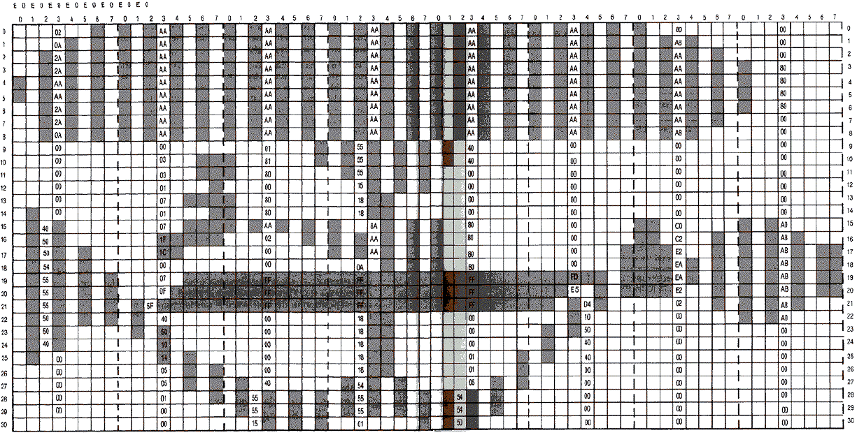
Download RASTER.EXE (Executable program)
Download / View RASTER.LST (Assembler listing)
Download / View RASTER.S (Source file)
Download RASTER.OBJ (Object file)
Download / View RASTER.RAW (As printed in book)
Sound
Sound complements graphics in nearly all arcade-style games. While most people think of sound effects as the only necessary sound, the addition of an original background score can contribute greatly to a game's overall popularity. In either case, the Atari, with its four-voice sound chip, is well-suited to the task.The Atari computer has four independent voices that can vary in pitch by more than three octaves. The tone can vary from very pure to highly distorted. In addition, each voice has its own loudness level, completely independent of the television's volume setting.
BASIC's Sound Statment
In BASIC, the SOUND statement takes the following form:SOUND Voice, Pitch, Distortion, Loudness
The first parameter Voice is simple. There are four voices or channels whose numbers range from 0-3. It takes a separate sound statement to activate each channel. Initially, at leas tin BASIC, they are all off at anytime, but anyone can be selectively turned off by setting Pitch, Distortion, and Loudness for that voice to all zeros.
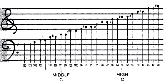
Pitch can vary between 0 -255. The value'N' is used in a divide circuit. For every N pulses coming in, one pulse goes out. As N gets larger, the output pulses become less frequent and make a lower note. A value of 121 produces a middle C tone. A pitch of 60 produces a C tone one octave higher, and a pitch of 243 produces a C tone one octave lower. Pitch values around 3 approach the edge of human hearing and may not be audible on a television speaker that lacks a tweeter.
The Atari computer produces both pure and distorted tones. The term distortion is actually a misnomer. All of the sound waves on the Atari are square waves. Distortion doesn't occur because of a degradation of the wave form like in harmonic audio, but by selectively removing pulses from the waveform. A more appropriate term would be noise. Distortion values of 10 and 14 generate pure tones. Other even-numbered distortion values (0,2,4,6, and 12) introduce different amounts of noise into the pure tone. The quality of the sound depends on both the pitch and the distortion. Some combinations, mainly distortion 12, combine to produce an undistorted secondary tone with harmonic overtones.
Loudness is controlled by the fourth number in the SOUND statement. The value varies from 0 (silent) to 15 (loudest) and is fairly linear for a single voice. The apparent loudness is affected by pitch. High-pitched sounds seem quieter than low-pitched sounds. If you are working with multi-channels, the sum of all four channels should not exceed thirty-two or it will overmodulate the audio output. The sound produced tends to actually lose volume and assume a buzzing quality.
Sound Duration
Since the SOUND statement lacks a duration parameter, sound can be turned on and then off by using an empty FOR ... NEXT loop as a delay. It is largely experimental but empty FOR ... NEXT loops iterate at approximately 450 times per second. A loop that goes from 1-225 would cause a delay of half a second. Thus, the following three lines would turn on a tone, let it sound for onehalf second, then turn it off.100 SOUND 0,121,10,10 110 FOR I=1 TO 225:NEXT I 120 SOUND 0,0,0,0
Sound Effects
Simple sound effects are created largely by trial and error. Many use FOR ... NEXT loops to either vary the pitch or vary the volume. Some do both. The pistol sound in the blocks game in Chapter 5 varies the volume. The bonk sound of the brick being removed is similar but at another low pitch. Both sounds use distortion or noise to achieve their effect.100 REM - PISTOL SOUND 110 FOR L=10 TO 4 STEP -0.25 120 SOUND 0,10,0,L 130 NEXT L 100 REM - BONK SOUND FOR KNOCKING OUT BRICK 110 FOR L=15 TO 0 STEP -0.5 120 SOUND 0,20,2,L 130 NEXT LIt is also possible to vary both the pitch and the volume simultaneously in a loop. The following example simulates the sound of a falling bomb. It begins with a high pitch and gradually changes to a low pitch, followed by the thumping sound of an explosion.
100 REM - FALLING OBJECT
110 FOR L=30 TO 200 STEP 3
120 SOUND 0,L,10,L/25
130 FOR K=1 TO L/10:NEXT K
140 NEXT L
150 SOUND 0,20,0,14
160 SOUND 1,255,10,15
170 FOR K=1 TO 150:NEXT K
180 SOUND 1,0,0,0
Most sound effects have to be placed in a larger loop with the graphics or player-missile commands, or motion will stop while the sound routine runs. The problem is that this method often alters the time delays and preset durations of the sound effects. Worse yet, the location of these routines within the program changes the result. This occurs because BASIC must search its line number list whenever it encounters a branch or GOTO instruction. Obviously, it finds line numbers at the beginning of the program before it finds line numbers near the end. The only real solution to the problem is to run your sound routines in the VBlank period, and this approach requires Machine language programming skills.
Sound-Assembly Language
The POKEY digital I/0 chip controls the audio frequency and the audio control registers for all four sound channels. The AUDF# (audio frequency) locations are used to control pitch, and the AUDC# (audio control) locations are used to control distortion and volume. The sound locations are as follows, and they are write registers only:AUDF1 = $D000 AUDC1 = $D001
AUDF2 = $D002 AUDC2 = $D003
AUDF3 = $D004 AUDC3 = $D005
AUDF4 = 3D006 AUDC4 = $D007
Frequency values range from $00 to $FF. POKEY actually increments this number by one before sending it to its divide by "N" circuit. For every N pulses coming in, one pulse comes out. Thus, the higher the value of N, the lower the tone. The rate of the pulses depends on the POKEY clock.
AUDC1-4 Sound Registers
The AUDC1-4 locations control both distortion and volume. The bit pattern is as follows:
The upper three bits control the distortion. Distortion is produced by first dividing the clock value by the frequency, then masking the output using the various poly counters specified by the bit pattern. The result is finally divided by two. Poly counters or polynomial counters are actually shift registers that produce various degrees of distortion in random but repeatable sequences. Since they are repeatable, they are predictable and are useful for generating sound effects. In general, the tones become more regular or recognizable with fewer and lower poly counters masking the output. The 17bit poly counter is useful for white noise effects like a waterfall, while the 4-bit poly counter is useful for a motor sound.
BIT	7	6	5
	0	0	0	5-bit, then 17-bit polys
	0	0	1	5-bit poly only
	0	1	0	5-bit, then 4-bit polys
	0	1	1	5-bit poly only
	1	0	0	17-bit poly only
	1	0	1	no poly counters (pure tone)
	1	1	0	4-bit poly only
	1	1	1	oo poly counters (pure tone)
AUDCTL Register
In addition to the independent channel control bytes (AUDC1-4), there is one other register, AUDCTL at 53768 or $D208, that affects all of the channels. Each bit in AUDCTL is assigned a specific function.Bit Description 7 Makes the 17-bit poly counter into a 9-bit poly 6 Clock channel one with 1.79 MHz 5 Clock channel three with 1.79 MHz 4 join channels one and two (16 bit) 3 join channels three and four (16 bits) 2 Insert high pass filter into channel one, clocked by channel two 1 Insert high pass filter into channel two, clocked by channel four 0 Switch main clock base from 64 KHz to 15 KHzShifting the 17-bit poly counters to 9-bit poly counters by setting bit 7, will create more repeatable sound patterns rather than white noise-type patterns. Setting the channels to a higher clock frequency (setting bits 5 and 6), will produce higher tones. Likewise, setting the bit 7 from 64 KHz to 15 KHz will produce much lower tones.
If you couple two of the sound channels by setting either bits 3 or 4, you reduce the number of channels to two but gain increased tonal range. Normally, you get a five octave range using the eight bits of a single channel, but the combined 16-bit register increases the tonal range to nine octaves.
Sometimes you may encounter problems POKEing sounds in BASIC or in Machine language without initializing the sound registers. BASIC requires a null sound statement, i.e., SOUND 0,0,0,0. In Machine language you need to store a 0 at AUDCTL ($D208), and a 3 at SKCTL ($D20F).
Background Music
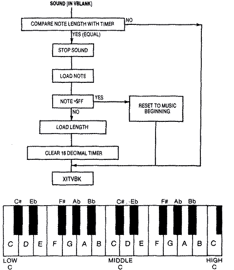
One of the most pleasing uses of sound is to play musical tunes quietly in the background, during many games or at least use them to enhance an animated title page. Such routines normally run in the Vertical Blank period so that the note lengths remain accurate. Generally, you store the notes and durations of the tune in a table. The Atari reads the note and its corresponding duration from the table. It then turns on the note and sustains it until the timer at $14, which counts in jiffies, reaches the value set by the duration. At that point the note shuts off and the computer reads the next note and duration. Two consecutive notes with the same pitch sound like they run together as a much longer note. It is often necessary to place a zero pitch lasting two jiffies between the notes. With this method, it is very simple to play an entire musical score without affecting the play mechanics or speed of a game. Be careful that you don't use and reset that timer elsewhere in the game.We use the value of $FF for the note as a flag to indicate the tune is finished. While it could be used to conclude the piece, we use it to reset the pointers to the table so that the music repeats endlessly.
The lengths of the different notes is summarized in the table below:
NOTE		JIFFIES
Sixteenth	8
Eighth		15
Quarter		30
Half		60
Rest		60
(The book indicates a code sample should be inserted here, but it is missing.)
Sound Effects
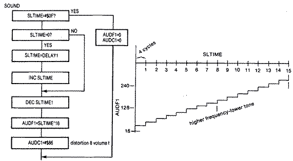
Explosion sounds are simple to implement in Machine language within the Vertical Blank routine. Basically, you need a very irregular rumbling sound that slowly decreases in volume. Setting the distortion to zero sets up 17bit poly counters that produce quite irregular sound. The duration of the sound is controlled by a timer that counts down every jiffy. This timer can also control the volume level so that it decreases as a function of the value of the timer. For instance, if the sound is to take one second, SEXTIME, short for Set Explosion Timer, is initially set to 64 and is decremented every jiffy. If VOLUME = SEXTIME / 4, then the volume will decrease from 16 to 0 as SEXTIME counts down to 0. The code follows:SOUND3 LDA SEXTIME ;CHECK EXPLOSION TIMER FLAG BEQ .1 ;IF AT 0, NO SOUND DEC SEXTIME ;COUNTDOWN LSR ;DIVIDE BY 4 TO GET VOLUME 16-0 LSR STA AUDC4 ;TELL POKEY NEW SOUND VOLUME ;UPPER NIBBLE (DISTORTION = 0) LDA #$40 ;TONE .1 RTSLaser fire can be simulated by rapidly changing the frequency from a high pitch to a lower one in discontinuous jumps while using a distortion set at 6. This produces a more staccato sound than a smooth frequency transition. You can implement this effect by making the timer, SLTIME, short for Set Laser Timer, a function of the frequency. If Frequency = SLTIME * 16, then each time SLTIME is incremented, the tone will jump in increments of 16. Remember, the higher the N in the divide by N he lower the tone. The problem here is that the sound is much too short if to increment simply from 1 to 15. Therefore, a secondary loop delays each tonal jump by 4 cycles. The entire sound routine takes 60 jiffies rather than just 15 jiffies. The flowchart and code are below:
SOUND      LDA SLTIME     ;CHECK LASER TIMER FLAG
           BEQ .3         ;IF 0 EXIT
           CMP #$0F       ;TIMER GOES FROM 1 TO 15
           BNE .1
           LDA #$00       ;TURN SOUND OFF
           STA AUDF1
           STA AUDC1
           RTS
.1         LDA SLTIME1     ;CHECK DELAY TIMER
           BNE .2          ;IF NOT 0 COUNTDOWN TILL IT IS
           LDA DELAY1      ;GET NEW DELAY VALUE
           STA SLTIME1     ;STORE IT
           INC SLTIME      ;INCREMENT MAIN TIMER
                           ;(THIS IS ALSO OUR FREQUENCY VALUE)
.2         DEC SLTIME1     ;OUR FREQUENCY VALUE
           ASL             ;MULTIPLY BY 16
           ASL
           ASL
           ASL
           STA AUDFI       ;NEW TONE VALUE
           LDA #$86        ;DISTORTION 8, VOLUME 6
           STA AUDC1
.3         RTS
Return to Table of Contents | Previous Chapter | Next Chapter

