9 Converters: Between Apple and Atari
If you or your friends have Atari game systems and an Apple computer, you
might want to use your favorite Atari joystick to play games on the Apple.
Or maybe you want to play games on your Atari using an Apple joystick. With
the two converters described in this chapter you can have both these options.
There are some limitations, however. The Atari-type joysticks
have a digital output, so you can use them on the Apple for only the simplest
games, like Snoogle, for which the joystick directs the movement of a character.
For the many arcade games that require only digital input, Atari joysticks
are much faster than conventional Apple joysticks.
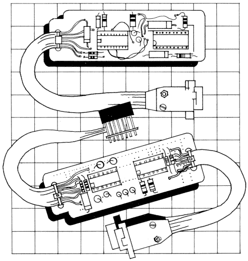
We will cover the construction of two small circuit boards
that function as converters: the first one, an Atari-to-Apple converter,
plugs into an Apple computer. You plug your Atari joystick into this converter
to play fast-action arcade games on the Apple. The second converter plugs
into an Atari system so that you can plug an Apple joystick into it. Now
you can play Atari games with your Apple controllers.
The Atari-to-Apple converter will greatly increase your
speed in playing arcade games on the Apple, especially if it is used with
homebuilt Atari paddles like the Tipping Disk (see chapter 5). Consequently,
we expect that there will be greater interest in this first type of converter.
The second converter, the Apple-to-Atari, is included because there is educational
value in making up the circuit. But even more important, newly developed
flight simulator or race car games for Atari-type systems will greatly benefit
from being played with the steering wheel and foot pedal designs given in
this book. Then your Apple-to-Atari converter will provide an exciting new
realism when you play these games.
Both of these boards are good beginning electronics projects.
Each has one or two integrated circuits, a few components, and some cables
and plugs. Each is easily assembled on a small piece of general purpose printed
circuit board. The parts are inexpensive and easy to obtain.
CHARACTERISTICS OF APPLE AND ATARI JOYSTICKS
The Apple joystick and the Atari joystick are two completely different devices.
The Apple joystick has two lever-controlled pots and a pushbutton, while
the Atari joystick is a collection of five pushbuttons, four of which are
mechanically connected in two pairs. The Atari-to-Apple converter must make
pushbutton closures look like changing pot values. The Apple-to-Atari converter
must make changing pot values look like switch closures. In addition, there
are two other differences between these joysticks that may cause some confusion
when you build these converters.
First, the Apple joystick has its common connection (one
side of each pot and each pushbutton) connected to the +5 volt supply line.
The common connection for the Atari joystick (one side of each switch) is
normally connected to the ground wire. The easiest way to design each of
these connectors was to make the common connection of the type required by
the host computer. This means that pin 8 of the Atari connector, which normally
would be connected to ground, is connected to the +5 volt supply (pin 1)
of the Apple game plug on the Atari-to-Apple converter.
The second difference is that the connector on the end
of an Apple joystick cable has pins on it, so it is defined as a plug. The
connector on the end of the Atari joystick cable has holes in it, so technically
it is a socket. We have used the correct terms in the hope that you will
order the correct parts. If you get confused, blame Atari, since they have
installed a socket where you normally expect to find a plug.
CONSTRUCTION
Each circuit is made up from one-third of a printed circuit board (Radio
Shack #276-154). You can mount the board in a small plastic box like a cassette
tape holder or inside a block of flexible packing foam. To cut the circuit
board, score it deeply with an X-acto knife and break it over the edge of
a table. Drill the holes for the wire ties with the end of the knife and
file all the circuit board edges smooth. Mounted on the board are several
resistors and capacitors and sockets for the chips. Both boards draw the
small amount of power they need from the host computer.
Most of the connectors for both converters are mounted
on short pieces of cable. The Apple-to-Atari converter does have one socket
for the Apple joystick; this socket is mounted directly on the board rather
than on a cable.
THE ATARI TO APPLE CONVERTER: CIRCUIT THEORY
Figure 9-1 is a sketch of the Atari-to-Apple Converter without an enclosing
box. Since this simple circuit can handle two joysticks, giving you the option
of playing two-person games, the sketch shows plugs for two Atari joysticks.
If you won't be playing such games you can install only one connector and
save a little money. The circuit requires two chips, one capacitor, and fourteen
resistors.
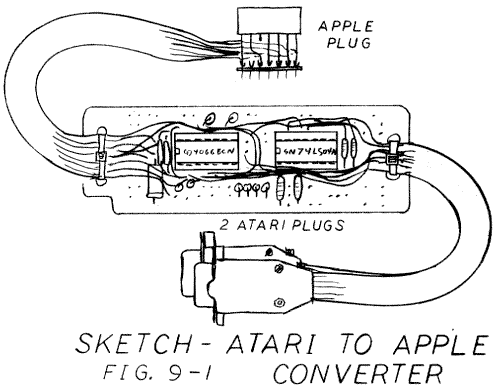
Figure 9-2 is a simplified schematic of the circuit that will help you understand how the card works. As noted, two chips are used. The 74LS04, a digital chip, has six inverters. If the input to an inverter is high (+5 volts) then its output goes low (nearly 0 volts), and vice versa. The second chip, the 4066, is a special purpose CMOS chip. It acts like four small single-pole, single-throw relays. If one of its control lines is brought high (+5 to +15 volts), then one of the relays closes and conducts electricity. If the control line is low (0 volts), then the relay is open and does not conduct.
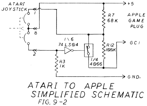
The Atari joystick has two internal normally-open switches
that correspond to the directions up and down. For the Apple to read these
two switch closures they must be converted to pot readings between 0 and
150K.
Depending on the position of the Atari joystick, the
game control circuit may read 68K (R7), 0, or 168K (R7 + R12). These resistive
values are read as 128, 0, and 255 by the Apple, and the program interprets
them as center, up, and down.
With the handle in the center position, R7 is in the
circuit but R12 is bypassed by one section of the 4066, so the reading is
128. If the handle is pushed up, the switch in the joystick bypasses R7 and
the reading is 0. If the handle is pushed down, the section of the 4066 opens
and the reading is 255.
The inverter in the 74LS04 and the pull-down resistor
R3 make the section of the 4066 operate the opposite of the down switch in
the joystick: when the down switch is open the 4066 section is closed and
vice versa.
This circuit is repeated for the left and right switches.
Since there are four switches in the 4066 chip and six inverters in the 47LS04
chip, you can control two joysticks with just these two chips simply by adding
a few more resistors and a second connector.
THE ATARI-TO-APPLE CONVERTER: WIRING
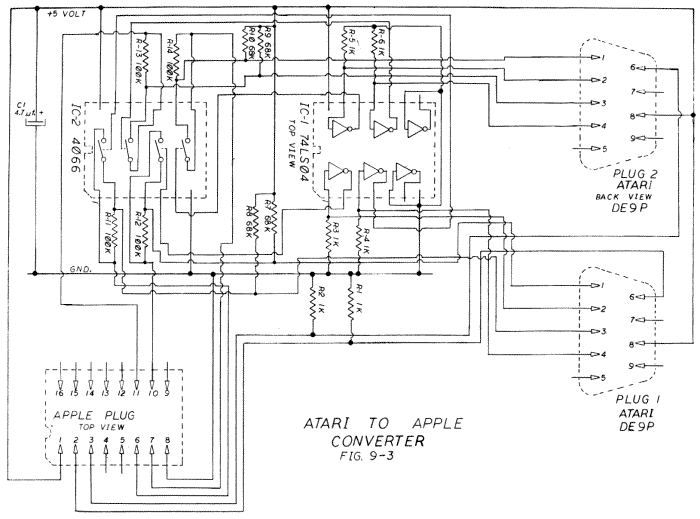
Figure 9-3 is the complete schematic of the Atari-to-Apple converter. Once
again, follow the procedures outlined in chapter 14 for checking your wiring
by coloring in two copies of the schematic. The Apple plug is a 16-pin DIP
header and is shown as it appears from the top. The Atari connectors are
shown from the back as they will appear when you solder them.
A word of caution: the 4066 is a CMOS chip and these
are easily damaged by static electricity. Leave the 4066 in its protective
package until you have completed the circuit and thoroughly checked it out.
It is imperative that you use a socket on the board for this chip.
We used #24 solid wire from a scrap of telephone cable
for jumpers on the board. Ribbon cable was used for the cables to the connectors.
The cable for the Apple plug requires eight conductors, but we doubled up
the +5 supply and ground, so ten conductors were installed. Two 6-wire runs
of cable were used for the Atari sockets.
Double check your work before applying power to the circuit.
Color in the second copy of the schematic, using an ohms meter to trace the
wires. When everything checks out, plug the two chips into their sockets
on the board, making sure the #1 pins are in the correct places, and install
the plastic hoods on the Atari connectors. The hoods have small plastic tabs
that may have to be filed down. They also come with mounting bolts, which
aren't needed for this project.
To test the converter, turn off your computer, plug in
the new unit (without a joystick attached to it), and turn the computer back
on. If the computer does not start up exactly as usual, turn it off immediately
and recheck all your work. When the circuit checks out, turn off your computer,
plug in an Atari joystick, and turn on the computer again. Now run the Controller
Checkout program from the software section and check out the game paddle
reading of your new adapter and joystick combination.
THE APPLE-TO-ATARI CONVERTER
Figure 9-4 is a sketch of the Apple-to-Atari converter. If an Apple-style
joystick or set of paddles is plugged into the empty socket on this board
and the Atari socket is plugged into an Atari game port, the Apple joystick
will perform like an Atari joystick.
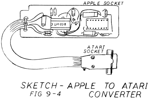
The mechanical construction of this converter is quite
similar to the one just described. It is built on one-third of a general-purpose
circuit board and has one chip, twelve components, a cable and socket to
connect to the Atari, and a simple DIP socket for the Apple joystick.
Figure 9-5, the simplified schematic, shows that this
converter works on completely different principles than the first one. The
pot in the Apple joystick is used in a resistive bridge with R1 so that the
voltage on pin 1 varies with the pot setting. Capacitor C3 reduces electrical
noise.
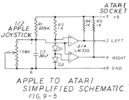
The LM339 chip contains four voltage comparators, each
with two inputs and one output. They compare the voltage on one of their
inputs with a reference voltage on the other input. They produce a digital
output to indicate whether or not the input voltage is greater than the reference.
The pull-up resistors R4 and R5 make the outputs look like the switch closures
of a standard Atari joystick.
The diodes D1 and D2, along with resistor R3, provide
two reference voltages (0.7 volts and 1.4 volts) for the comparators. Here
we are using a property of a real diode, its forward conductance voltage
drop, which a theoretically ideal diode would not have. If we passed a small
current through an ideal diode there would be no voltage drop. If we pass
a current through a real silicon diode, however, there is a drop of about
0.7 volts, and this drop changes very little with fluctuations in temperature
and current.
Two comparators in the LM339 compare the voltage from
pot 1 with our two reference voltages and put out the correct digital signals
for the joystick position: left, right, or center. A similar circuit checks
pot 0 for the signals for up, down, or center.
You will have to adjust the circuit to use this converter
with joysticks that have correction caps. The resistive bridge circuit measures
resistance only, so if the pot is not 150K, resistors RI and R2 will have
to be changed. The correct value is about one and a half times the value
of the joystick pot.
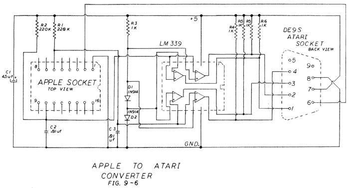
Figure 9-6 is a detailed schematic for wiring the converter.
Be sure you lay out the #1 pins on the chip and socket in the correct direction.
The plus lead of capacitor C1 must go to the +5 supply. On the LM339, the
pins used for the +5 and ground are not those commonly used for digital chips
(the 74LS series), so double check them before applying power.
Double check your wiring, do not plug any electronic
device into a live socket, and be quick to turn off the Atari if everything
doesn't look absolutely right.
FINISHING UP
As mentioned earlier, the circuit boards should be mounted in small boxes
to prevent the wires from shorting. You could use cassette tape boxes, cutting
out holes for the cables with a coping saw and small files. Alternatively,
you could encase the circuit in a foam block, as was described for the Multiple
Socket Extension (see chapter 3). Or you could purchase a small electronics
box, fit the circuit board into the box before mounting the components, and
drill and file out holes for the cables. Depending on the box you use, you
may have to cut the PCB and arrange the components differently from those
of the prototype.
From the standpoint of their electronics, these two converters
are the most sophisticated projects in this book. A little care in their
construction, however, will give you an excellent lesson in electronics and
a device that will greatly increase your enjoyment of your other controllers.
| Parts List Atari to Apple Converter |
||||||||||||||||||||||||||||||||||||||||||||||||||||||||||||||||
|
||||||||||||||||||||||||||||||||||||||||||||||||||||||||||||||||
| Parts List Apple to Atari Converter |
||||||||||||||||||||||||||||||||||||||||||||||||||||||||||||||||
|
||||||||||||||||||||||||||||||||||||||||||||||||||||||||||||||||
|
Return to Table of Contents | Previous Chapter | Next Chapter

