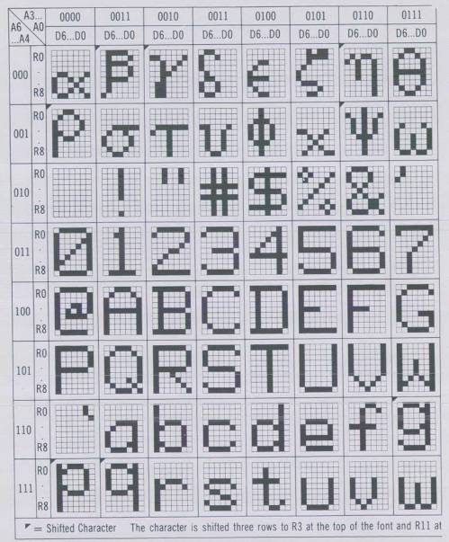
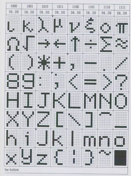
THE CHARACTER GENERATOR ROM
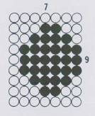
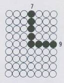
Most computers today use a special device called a character generator ROM to convert the ASCII bytes to a tiny dot matrix pattern for displaying on the tv screen. This dot matrix can have a density ranging from 5×7 (the most coarse and not allowing lowercase) to 10×12 (the most dense and allowing all symbols of the alphabet). As the resolution of the dot matrix of the character increases so does the cost of the ROM chip; so the 5×7 and 7×9 matrixes have become popular, the 7×9 in Fig. 2-4B having uppercase, lowercase, and Greek math symbols. Besides cost, another factor that limits the character matrix density is maximum dot frequency permitted by the tv. This simply means that the internal circuits of the television set will not allow a dot pattern to be resolved if there are frequency components in it which exceed about 6 MHz.
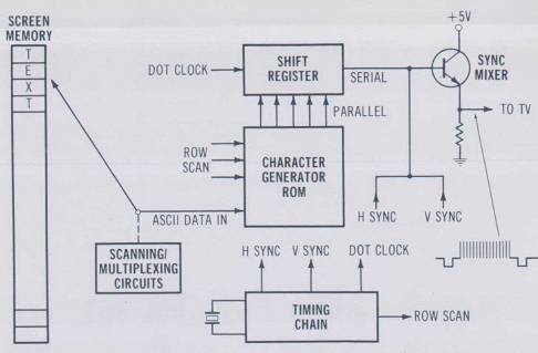
The basic trick to making a memory-mapped display work is shown in Fig. 2-5. The large switch shown to the left of center in the figure represents circuits that scan the bytes in the screen memory and send them to the character generator ROM.
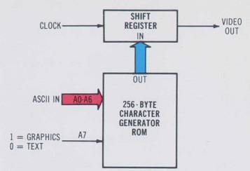
The purpose of the character generator ROM is to accept the ASCII bytes from memory and convert them to a row of dots for the character that these bytes represent.
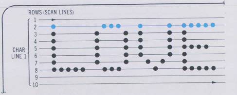
The secret to understanding how the video circuits work is to realize that the ROM puts out all the dots for one row of all the characters on a single line of text on the screen (which might be 25 to 80 characters long. This is shown in Fig. 2-6. In this figure the top row of dots of all characters on the first line are being displayed. Each row here takes 63 μs. Characters in a line are presented to the ROM eight times, once for each row.
Thus each character on a line of text is accessed from screen memory several times until all the rows are laid down. If the characters are on a 5×7 matrix then each character is accessed seven times, one time for each of the seven rows. The more rows in the character matrix, the better and faster the video circuits must be.
Referring back to Fig. 2-5, the box labeled timing chain generates horizontal and vertical sync pulses just like the kind the broadcasting people generate, along with a row scan signal for the character generator ROM and a high-frequency dot clock signal for driving the shift register. The shift register takes the parallel row of dots from the ROM and converts it to a serial bitstream called the raw video. The transistor is a simplified version of a mixer which adds the horizontal and vertical sync to the raw video. Since everything is digital all signals can be synchronized to the high-frequency dot clock and we get a rock-solid display.
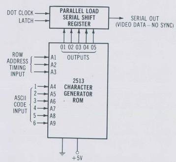
Fig. 2-7 shows a typical low-cost character generator ROM called the 2513. It lacks lowercase and therefore uses only 64 of the 128 ASCII characters. This is why there are only six character inputs to the ROM (two raised to the sixth power is 64). The three remaining inputs (A1, A2, A3) generate the seven row addresses for the characters in the ROM. The dot clock shifts the latched word out serially to form the video data stream.
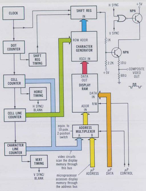
A complete video display circuit block diagram is presented in Fig. 2-8. Here we see that the timing chain (the five boxes on the left) must keep a count of the character cell, row (cell line), and line. In addition the figure shows the multiplexer, which allows either the video circuits to scan the RAM and put data on the screen or the computer to access the screen memory to write new data or sometimes to read old data.*
Return to Table of Contents | Previous Section | Next Section