DETAILED DRAWING AND DIGITIZING TABLES
Although high screen density means increased realism, stop for a moment and ask yourself how would you get a highly detailed drawing onto the screen of a high-resolution graphics computer? The answer is not as simple as it would seem.
Graphics Input Devices
Today there are about three different approaches to entering graphics information in a computer:
- Keyboard Entry—The simplest method for entering graphics data is by using the keyboard and a program that lets you turn individual dots on and off or draw lines by typing in their coordinates. Obviously this approach is very time consuming, but it has the redeeming advantage of needing no extra hardware. If the computer offers shape tables like the Apple, the keyboard can be used to build shapes by specifying vectors instead of coordinates. Again this is time consuming but in some cases it may be adequate.
- Light Pens—A light pen is a small pen-sized device that contains a light-sensitive photocell in its tip and connects to the computer via a cable. With sufficient circuitry and software the position of the pen on the screen of the computer can be determined. The limits of resolution of the light pen are set by the resolution of the screen itself. This means we can't expect much more than to be able to draw on the screen. Further, if you wish to trace a drawing with the light pen from, say, paper to the screen of the computer you must get the drawing onto clear Mylar, tape it over the screen, and then trace it out on the screen with the pen.
- Digitizing Tables—A digitizing table consists of a flat table surface about 15 inches by 15 inches (38 cm by 38 cm) square, with a penlike device connected to it via a cable. The table contains circuits that allow it to measure the position of the pen to an accuracy of 0.005 inch (127 μm)! A typical digitizing table has an active area of 11 by 11 inches (28 by 28 cm). The digitizing table sends the computer over 100 coordinates per second and each coordinate can be a number from 0 to 2048. This not only allows extremely accurate data to be entered but means that pen motion will be fluid and smooth. With a digitizing table you can trace highly detailed drawings and have them scaled to any proportions and then echoed on the screen. You can trace the path of a trip on a map and get precise distance. You can trace out a polygon and have the area measure out super-accurately. You can even create schematics on the screen and use the pen to move logic gates, draw wires between the gates, etc. This last application is called computer aided design. Later a demonstration program will be presented that will illustrate this most incredible application.
The Talos Digitizing Table
The digitizing table used in this book is made by Talos Systems and represents a good example of the state of the art for low-cost home computers. The table works with the PET 2001, the Radio Shack TRS-80, and the Apple II and costs under $450. Remember that although these devices have been used for some time in the industry, they have only recently become available for the low-cost home computers.
The Talos digitizing table consists of a flat table approximately 15 inches square and a small “pen” that is attached to the table through a cable. The “pen” isn't really a pen, but instead contains a tiny transmitting device in its tip. The tip also contains a tiny switch so the computer can tell when the pen is being pressed down on the table.
The basic job of the table is to send very accurate data to the computer that represent the position of the pen in the X, Y plane of the table. It is the job of the computer software to decide what to do with this data. This position data is usually sent to the computer many times per second.
There are several ways a digitizing table can work, but in general the pen acts like a transmitter to the table, and the table like a receiver. The table contains circuits that use the transmitted signal to accurately determine the location of the pen in the X-Y plane.
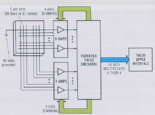
There are basically three methods for detecting pen position: sonic, magnetostrictive, and pure electronic. The Talos table used in this book uses a patented differential current measurement technique (see Fig. 3-32). The pen sends a 100-kHz signal to the table via a tiny coil in the pen tip. Under the table is a double-sided pc board with parallel lines (0.2 inch or 0.5 centimeter apart) running horizontally on one side and vertically on the other. IC amplifiers are connected to one end of each wire. The wire forms a one-turn coil to the amplifier input. Analog circuits scan the wires 100 times per second, first all the X-side wires, then all the Y-side wires. The circuits then use a special differential current subtracting technique that accurately determines the position of the pen between two wires to 0.005 inch (127 μm).
The table then sends the Apple interface (or any interface that is connected to the table) 16 bits of data: 14 bits of X or Y, a pen up or down bit, and a bit indicating if the data is X or Y.
The Apple interface uses 12 bits of this data, giving an overall range of 2048 points in either axis. Dividing this by 200 points per inch (about 78 per centimeter) gives a maximum range for the Talos unit of about 10.24 inches (26 cm).
Using a Digitizing Table with BASIC
In order to use the digitizing table with BASIC programs on the Apple a special assembly driver routine must first be loaded into memory. The purpose of the routine is to put the incoming data from the table into five locations in memory. The routine is called from BASIC with a CALL instruction. When the routine is called it returns two bytes of X data, two bytes of Y data, and a pen up/down byte. Our BASIC program then uses the PEEK function to convert these values to variables. First, on p. 159 is the 53-byte assembly driver routine for the Talos table.
The listing was produced using the Apple disassembler and was printed on an Axiom printer.
There are several ways to get the driver routine into memory. Considering that the routine is short (53 bytes) the best way is to convert the hex bytes to decimal equivalents in a DATA statement and then POKE them into memory with a FOR..NEXT loop.
0306- AD 00 C4 LDA $C400

0309- AC C0 C0 LDY $C0CO

030C- 2C 00 03 BIT $0300

030F- F0 F5 BEQ $0306

0311- 29 OF AND #$0F

0313- 8D 01 03 STA $0301

0316- 8C 02 03 STY $0302

0319- AD 00 C4 LDA $C400

031C- AC C0 CO LDY $C0C0

031F- 2C 00 03 BIT $0300

0322- D0 F5 BNE $0319

0324- AA TAX

0325- 29 10 AND #$10

0327- 8D 05 03 STA $0305

032A- 8A TXA

032B- 29 OF AND #$0F

032D- 8D 03 03STA $0303

0330- 8C 04 03 STY $0304

0333- 60 RTS

0334- E6 41 INC $41
The Talos digitizing table returns five bytes of data when the driver subroutine is called—two bytes of X, two bytes of Y, and a pen up/down byte. Since X and Y are each larger than 255 (the largest number possible in one byte), it is necessary to split X and Y into two bytes called XLSB (least significant bits), XMSB (most significant bits), YLSB, and YMSB. The fifth byte is called PEN, and if PEN = 0, the digitizer pen is being pressed down, and if PEN = 16, the pen is not pressed down, or up.
The LSB of X and Y is a full 8 bits while the MSB of X and Y is 4 bits. This is a total of 12 bits for each axis, or 2048 decimal points. The results in memory look like this after doing a CALL DIG (assuming DIG = 774 and this is beginning of driver routine):
| Memory Location (Base 10) | Stored There |
| 769 | XMSB |
| 770 | XLSB |
| 771 | YMSB |
| 772 | YLSB |
To convert these bytes in memory to decimal coordinates for our BASIC program we use the PEEK function and a simple formula (shown here for X):
X = (PEEK(XMSB) * 256) + PEEK(XLSB)
where XMSB = 769 and XLSB = 770 have previously been given. The formula for the Y bytes is similar except we use YMSB and YLSB.
In order to use these values say for drawing in high resolution on the Apple we need the BASIC program to check for when the pen is pressed, read the new coordinates, and draw a line from the old coordinates to the new. We can perform a simple loop like this:
50 CALL DIG IF NOT PEEK(YMSB) THEN 27000

60 XNOW = ..... formula for X

65 YNOW = ..... formula for Y

70 RETURN

100 GOSUB 50: IF PEEK(PEN) THEN 100

...

program to do something with new coordinates

...
Here the statement in line 100 is a GOSUB 50 that causes the driver to execute and the new X, Y, and PEN values to be placed in to memory. Next the PEEK(PEN) statement inside the IF…THEN statement checks if the PEN is up (greater than 1) or down (0). If the pen is up, the statement loops back to call the driver again. If the pen is down, then the code following the IF…THEN statement is executed, which could be HPLOT TO statements which draw a line or plot a point.
Since the returned values are as large as 2048, we must scale them by dividing each coordinate by a constant.
Using the Digitizing Table: Talos Demonstration
Using the digitizing table can best be illustrated with a demonstration program available from Talos Systems. The program is designed to run on any 16K Apple with Applesoft on ROM and a Talos DIG-I-KIT-IZER or SIMPLE-ONE.
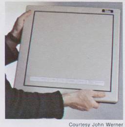
The demonstration program for the digitizing table was written by Talos Systems and comes free with the Talos table. The program consists of six demonstrations described below. The entire demonstration program is loaded and then the bottom area of the table becomes a main menu area used to select the desired demo with the pen. Fig. 3-33 shows the table with the menu taped on.
Digitize Raw Coordinates
This program simply outputs the X and the Y coordinate values when the pen is pressed down on the table. As the pen
is moved about the table the numbers displayed on the screen are updated to represent the new pen position. The demonstration is useful for showing the dynamic range of the digitizing table.
Distance
This program is used to accurately measure distance, such as for trips, perimeters of property, etc. For example, a map can be placed on the table and the pen touched along the path you might travel. Each time the pen is touched on the path, the new distance accumulates at the bottom of the screen. When done you can use the map's scale factor as a multiplier to get exact miles. Keep in mind that the software has 9 digits, so you can be sure it is accurate. However, the table is only accurate to one part in 2048 or about 3½ digits of accuracy. To check the accuracy of the table a ruler was placed on the table. A point right above the 1-inch mark was touched and then a point above the 10-inch mark was touched with the pen. The table read out the distance 8.9933125 inches!
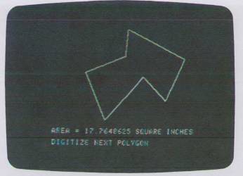
Area
The area program is extremely useful. You can trace out any polygon or irregular closed figure and the computer will print out the exact area. See Fig. 3-34.
The program relies on a simple algorithm for calculating area of a polygon given the coordinate points for the vertices as follows:
Area = 1/2 (X1 * Yn + X2 * Y3 .... + Xn - 1 * Yn + Xn * Y1 - Y1 * X2 - Y2 * X3 .... -Yn - 1 * Xn - YnX1)
This program can be used to calculate the cost of materials from a drawing, the area of a strange shape including curves, the area of a floor plan, and so on.
Music
This program shows how you can use the digitizing table as a music machine. The Y axis controls the pitch of the tone and the X axis controls the duration of the tone (the tone is pulsed on and then off). This rather unique application might be used in a game to teach manual dexterity. Since the pen position can be measured we have an objective measure of the user's movements. The game could be to chase the sound with the pen.
Color Painting
This is the original low-resolution graphics drawing program for the Apple that allows you to paint in low-resolution color from seven drawing colors and three screen colors. The pen is used to “dip” into the colors to select a color for painting.
Drawing
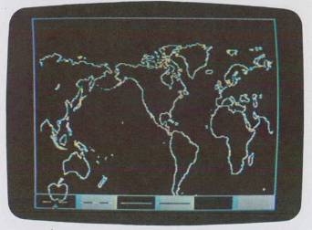
The drawing program allows you to create pictures on the screen in the high-resolution mode. Fig. 3-35 shows a map of the world in the drawing area of the hires drawing program.
A small crosshair moves about on the screen following the pen's movements on the table. When the crosshair is moved into a box in the menu area and then pushed down, the function described by that box is enabled and a duplicate image of the crosshair is latched in that box to indicate the function chosen. The broken line in either of the two left boxes of the menu puts the pen in the point mode, which means that when the pen is pressed points are output to the screen. The first box is for white lines and the second box for black. This is the mode for freehand drawing. The solid line in either of the next two boxes puts the pen in the line mode, which automatically draws lines between digitized points. These can be used for erasing black or white lines, or for drawing white or black lines. The last two boxes on the right select black or white backgrounds.
Once a drawing has been created in the drawing area it can be saved permanently on magnetic tape or diskette by storing the memory image from 2000 to 4000 hex (8192 bytes of screen memory in the Apple). Later you can recall the image from disk or tape for modification.
Computer Aided Design (CAD)
This is perhaps the most incredible application of the graphic computer and the digitizing table. The name of the demonstration is slightly misleading because you might think the computer does the designing. Sorry, it is not so. What the program does do is still incredible. It allows you to draw schematics on the screen of Apple in high resolution and is similar to systems sold by Calma and Calcomp.
The program is similar to the drawing program, but in addition it has a menu of electronic logic symbols including an AND gate, inverter, and OR gate. As shown in Fig. 3-36 these symbols can be used to create a detailed schematic of a logic circuit. The gates can be “captured” with the pen, and moved to any place on the screen and then locked there when the pen is removed. The spiral figure in the menu area is for rotating the gates to one of four directions.
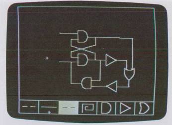
The point and line drawing functions can be chosen to connect outputs to inputs, to make connection dots, to draw resistors, and so on.
The schematic can be printed out on the Axiom EX-820 printer (a low-cost printer for the Apple) by doing a complete screen dump to the printer. Note that this is not an ordinary printer but instead contains special firmware for copying the high-resolution page.
With a little more work to the program you could have additional menus that contain analog components, resistors, capacitors, and a menu that contains labels such as Rs and Cs that can be placed on the schematic for identification.
One could create a generalized CAD program that allowed making custom shapes for the menu, such as pipe sections, engine parts, pumps and gears, and so on. The pen could be used to move the parts and stick them together as you wished—much easier than drawing by hand and erasing.
The final word would be to have the circuit we created actually start up and run! Imagine the effect this would have on technicians today.
Return to Table of Contents | Previous Section | Next Section