Examining the Display List
The display list is written in ANTIC machine language and is a program. Do not expect the operation codes, stored in the bytes of the DL, to match what you think they should be. For example, a "0" is not a graphics 0 instruction.
ANTIC instructions come in one or three byte sizes. The three byte instructions are really one byte instructions with 2 extra bytes of data. These 2 bytes of data specify a memory location and are examined together as one 16-bit address. The address can specify any location in memory. Since ANTIC needs to be able to go anywhere in memory, these are the instructions that enable it to do so.
One instruction is the number "2". It is a one byte instruction that tells ANTIC to generate a graphics 0 display block, and we will be seeing a lot of them. Let's go ahead and display the display list in your machine on the printer, or on the screen if you do not have a printer. (If you do not have a printer, change every LPRINT in the program to PRINT.) Enter and run program 4.
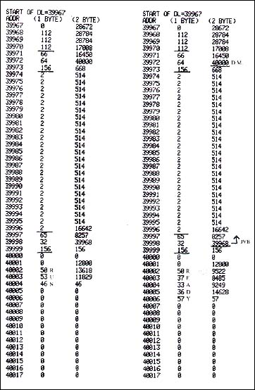
Your printout will look like Figure 11. If you have 48K of RAM memory in your Atari, it should be identical. Let's examine the program and see how it works.
Line 10 examines two locations in memory through the PEEK statement. You may want to go back and reread the chapter on memory concepts if you are getting lost. The locations are at addresses 560 and 561, and together they specify the start of the display list. They form a 16 bit address, so line 10 takes both 8 bit values and multiplies one by 256 in order to make the number a 16 bit value for us to use. This value is the memory address of the beginning of the display list.
Line 10 assigns START to the address in memory where the display list begins. The program prints the address in line 20 and a title in line 30. Lines 40, 50, and 60, display the next 50 bytes' memory location, value, and 16 bit interpretation of that value, since some of these bytes will be parts of 16 bit addresses. Examining our output, we see that the byte at address 39968 contains a value of 112. The next byte is also 112, and so forth.
We have marked the two 16 bit addresses in the display list. Other than that, you can ignore the 16 bit column, as does ANTIC. Only in 3 byte instructions does it take the last two bytes and combine them to form a 16 bit address. Remember our display list is only 33 bytes long in graphics 0. We have printed out 50 locations. Let's start at the top of the display and work down, seeing what ANTIC does with each instruction. You could think of this as a program with the memory locations as line numbers. Should your Atari have less memory than mine, the memory locations will be lower, but that is no problem. Everything done here can be applied to a lower memory Atari as well.
The first three bytes contain the value 112. Instruction 112 calls for a display block 8 scan lines high with no characters. This tells ANTIC to take a break, do nothing with display memory, and generate 24 background color scan lines (8 scan lines for each value of 112). Many televisions "overscan", and if we do not leave a border around the display area some of that area could be lost off the screen. The 112 instructions do not look to display memory. The next 3 bytes are all one instruction. They tell ANTIC where display memory is, and tell it where to get data if it is needed. The next 24 instructions (all with the value "2") are graphics 0 display instructions. They instruct ANTIC to generate 24 graphics 0 display blocks, using data from the display memory. The last instruction in the display list is executed over and over, in a loop. This particular instruction tells ANTIC to wait until the beginning of the next screen refresh, then go to the address given in the next two bytes. The 16 bit translation of those two bytes is 39968. If you look at the top of the display list printout, you will see that this is the start of the display list.
5 GRAPHICS 0
6 PRINT "READY"
10 START=PEEK(741)+256*PEEK(742)
20 LPRINT "START OF DL=";START
25 LPRINT "ADDR     (1 BYTE) (2 BYTE)"
30 FOR ADDR=START TO START+50
40 LPRINT ADDR,PEEK(ADDR),PEEK(ADDR)+256*PEEK(ADDR+1)
60 NEXT ADDR
Program 4
The fourth display list instruction told ANTIC where to look for the display memory. The 16 bit value is 40,000. That is the beginning of display memory.
Bytes 40000 and 40001 are 0's. A 0 in character mode is a space. There are two leading blanks for the left margin. The next 3 bytes contain data. They are the letters "R", "U", "N", displayed on the screen and in memory when this program was executed. If you were to PEEK farther into display memory, you would find that the first 40 bytes reflect the first line displayed in graphics 0, the next 40 represent the next line, and so on. The other listing reflects what a READY would look like in display memory.
If you have less memory, for example a 32K machine, the addresses are going to be different. Your printout will tell you where the display list and memory are located. Everything is identical, except that it is located in a different part of memory.
|
| Figure 11. |
Table of Contents
Previous Section: More Memory Secrets
Next Section: Modifying Display Memory