The Beginner's Guide to Character Sets
An important part of the design of the Atari computers was to obtain varied and interesting graphics displays. Atari designed into their machine as much software-controlled hardware flexibility as possible. In this way they hoped to achieve widely varied effects without changing the basic hardware.
We have covered a variety of playfield (i.e. display list generated) graphics and gotten familiar with player-missile graphics. Now we will cover another of the many playfield features, the ability to redefine a character set.
A character set is the table of shapes the Atari uses to define each character. This character set, or shape table is what makes an "A" character look different from a "B" on the screen. With the Atari, these shapes may be altered at will.
With most computers, you cannot change the characters the designers give you. The shapes are stored in ROM and cannot be modified except by creating a new ROM, a task beyond most of us. This places a limitation on those machines, for reprogramming character shapes is a powerful tool for certain applications.
If we are writing a program to teach the Russian language, we would naturally like to be able to write words in that language. But Russian has characters not found in English. With most machines, you are stuck at this point. Unless you use slow and clumsy high resolution graphics to draw characters, you cannot use the Russian characters.
On the Atari, it is easy to design your own characters. You can use new letters for the Russian lesson, and save yourself a lot of time and effort.
If you need some small figures on a character screen, but do not want to worry about mixing graphics modes, a character set might solve your problem. You can control dots the size of an individual graphics 8 pixel with custom characters, for that is the size dot characters are built from. You can even mix those special symbols in with your other text. For mathematicians needing special characters such as summation and integral characters, this could be a real help.
As soon as you begin to consider characters as graphics 8 figures drawn at high speed on the screen, more and more interesting possibilities will occur to you for the use of reprogrammed characters. We will review a bit about character shapes and generation, then learn how to modify them.
Character Shapes
The Atari plots letters and graphics on the screen using individual TV dots. It uses 320 horizontal dots and 192 scan lines for this purpose. Characters are 8 X 8 groups of dots, that is 320/8 or 40 characters across and 192/8 or 24 rows. There is no space on the screen between characters. Such space is provided for within the character shapes. This makes possible continuous script letters, which "flow" from one to the next with no interruption. It also enables screen graphics using characters that have no "breaks" in them.
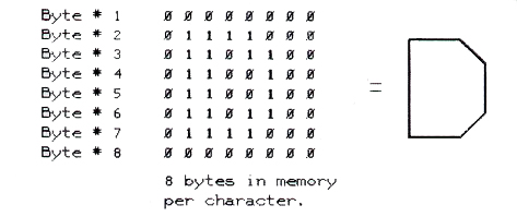
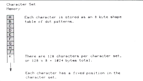
Character shapes are stored as an 8 X 8 group of bits. A lit dot is represented by a "1" bit, an unlit dot by a "0" bit (Figure 25). Since each horizontal "slice" of the character is 8 bits, the Atari's designers put each slice into one byte, for a total of eight bytes per character. There are 128 different possible characters, and they are stored all grouped together, so the complete "character set" is 128 X 8 or 1024 bytes long. (Figures 26 and 27).
Every time a character is displayed, the Atari consults this table.
| |
|
Figure 25. |
|
|
|
Figure 26. |
|
|
|
Figure 27. |
When ANTIC finds a display list entry to generate characters (modes 0, 1 and 2 to Basic users), it looks to the current location in display memory, kept in an internal ANTIC register. Let's assume graphics 0. One graphics 0 instruction means 40 characters are plotted in one row for one display block. In a character mode, one byte of display memory represents one character, so ANTIC fetches 40 bytes. Each character has a unique number, 0-127, and ANTIC uses that number to look up the character's shape in the character set.
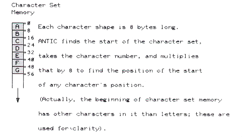
First, ANTIC must find the character set. That is easy. The character set is sent to ANTIC every sixtieth of a second by the operating system as part of the screen refresh process. It is controlled by location 2F4 Hex or 756 decimal. This location we will call CHBAS, for "CHaracter set BASe". The number in this byte, when multiplied by 256, specifies the start of the character set in memory. In the Atari, like all 6502 processor machines, memory is divided up into "pages". Each page is 256 bytes long, exactly corresponding to 8 bits of address. In a 16 bit address, the upper eight bits specify which page number, and the lower 8 bits specify which byte within the page. Because the character set always starts on an even page mark, we only need to tell ANTIC where to find the character set's first page. Next, we must find the group of 8 bytes within the character set that represent the shape for an individual character.
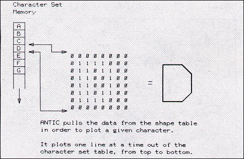
The character number in display memory, known as the "internal character set number" (this is not ATASCII!) is multiplied by 8. This is then added to the CHBAS*256 number to give ANTIC the starting address in memory of the particular character's shape table. When displaying the character, ANTIC takes the first byte of the shape table, displays it as 8 on or off dots according to the bits in the shape table, then moves down one byte in the shape table for the next line. After eight passes, it has moved down 8 scan lines and read 8 bytes and is finished with the character (Figure 28).
|
|
|
Figure 28. |
If we tell ANTIC the shape table began somewhere else in memory, it would look to the new location and start using whatever data was there to display characters. You will recall that earlier we told ANTIC that display memory was located in low memory, to watch it display pages 0 and 1 of memory, an area where there is all sorts of activity going on, as characters. This is the same idea. If the new area of memory happens to be a table of character shapes, redefined to what we want them to be, ANTIC will use them without complaint.
We cannot change the existing character set. It is stored in ROM (read-only-memory) and cannot be modified. So what we need to do is copy that ROM character set into RAM (Read-Write-Memory), where we can modify it, and then tell ANTIC to start looking to RAM for the character set. All we do (to change where ANTIC looks) is POKE a new page number in memory into location 756. A sixtieth of a second later, the operating system will give ANTIC that new value as part of the screen refresh, and it will start using it.
Our demonstration programs will demonstrate this process and show us how characters are stored.
Program 21 begins at the start of the unmodifiable character set the Atari normally uses, the ROM character set. It fetches 8 bytes per character, breaks each byte up into individual bits, and displays them as "0"s and "1"s. The program goes through the entire character set this way, displaying what the characters look like in binary patterns. See the listing for an example. You can see how ANTIC uses the "1" bits to plot lit dots and thus characters.
You are going to soon notice that characters are not stored in ATASCII order. They are in the order of the internal character set, which is a different thing. You can find a listing of the internal order on page 55 of your Basic manual.
|
Program 22 dumps the specified character to the printer; just type in the letter whose bit pattern you would like to be displayed. It is converted into an ATASCII number, then into the internal character set number, then displayed. This program is handy in showing how to convert from ATASCII to internal format. To find the right bytes in the character set, the internal number is just multiplied by 8 and added to the number that represents the start of the character set, which you will recall is just how ANTIC does it.
The character set we are currently looking at is in ROM, as previously mentioned. Let's learn how to move it to RAM to allow us to modify it. This will consist of three steps:
I. Finding a place to put it. We need 1024 free contiguous bytes of RAM.
2. Copying the ROM character set to RAM.
3. Changing the "pointer" ANTIC uses to find the character set from its old ROM location to the new RAM location.
Step 1 is tricky. To properly understand how to do this, we must delve into some Atari memory secrets.
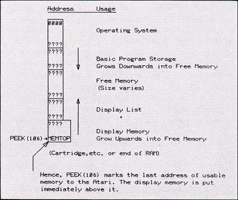
When the Atari is first turned on, a check is made to determine where RAM ends. This can be anywhere from 8K to 48K from the beginning of memory; it depends on how many memory boards you have installed. In location 106 decimal (6A hex) is stored the page number of the first byte of non-existent memory. In other words, 256*PEEK(106) is the address of the first byte of nonexistent memory.
|
Now the Atari uses the very top of RAM memory, wherever that might be, for the display memory and display list storage. Right below that is free RAM, and below that is Basic storage. (Basic and the graphics modes "grow" towards each other into free RAM when they use more memory). So whenever a graphics command is executed, and the Atari needs to set up a new display memory-display list, it checks location 106 to see where RAM ends. It then backs up the required number of locations and puts the display memory in (Figure 29). Think of memory location 106 as the Atari's "fence", used to find the end of memory.
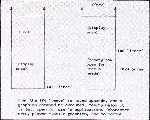
Now let's assume we POKE 106,PEEK(106)--4). This will move back the end of memory fence by 4 pages. Each page, you will recall, is 256 bytes, so that is 4 times 256 or 1024 bytes moved back. We then execute a graphics command, so the Atari will move the display memory list out of that 1024 byte area, behind our fence (Figure 30). In this way we reserve 1024 bytes for memory starting on a page border.
There are several advantages to getting 1024 bytes this way. It does not matter what size memory machine you have, as long as the minimum 1024 bytes are available. It does not matter how long your Basic program is or what graphics mode you are in. You can see it is quite a handy general purpose thing to have.
This is also the preferred technique to use when reserving memory for the Player-Missile bitmap area. 8 pages are required for a 2048 byte bitmap (single line resolution) or 4 for 1024 bytes (double line resolution). You will see this byte 106 modification in most articles on Player-Missile graphics.
We now know the beginning of the RAM area, and where the ROM character set starts (E000 Hex or 57344 Decimal). Let's copy the ROM character set to RAM (Program 23). This program moves the 106 pointer back 4 pages and copies the character set over. It takes a while; around ten seconds is needed to copy 1024 bytes. Basic just is not very fast at copying data.
|
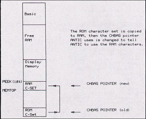
Finally, the CHBAS pointer is changed to reflect the page of the beginning of our new RAM area. ANTIC is now using the RAM character set (Figure 31).
Program 23 is not going to show you much, for ANTIC will still be displaying characters as usual. So let's watch the copy process in action. This time we will move the character set pointer first, then do the copy. Your screen will suddenly start displaying whatever junk is in memory at the start of the copy as the pointer is changed, then more and more letters will appear as Basic gets more and more character shapes copied into the RAM table. At the end of the copy, the screen will once again appear normal (Program 24).
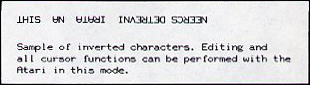
Program 25 presents an interesting variation. It copies characters from ROM and RAM upside down. It does this by copying the eighth byte of every character into the first byte of that character's new bitmap, the seventh to the second, and so forth. The result is that the new RAM bitmap is an inverted image of the ROM bitmap. This is a lot of fun. The characters will still be on the screen, and you can even edit them. They will just be upside down.
Program 26 shows another useful variation. It makes every character's last byte be a 255. or solid 1's. This puts a solid line at the base of the characters, and there is thus a line at the bottom of each of the 24 character rows. If you have been wondering how to underline a particularly important concept on the Atari screen, you have just found out how.
Program 27 illustrates another handy character set feature. We can POKE different values into the CHBAS pointer and thus switch between multiple character sets immediately. In program 27 we have two character sets, one normal, one flipped upside down. The program switches between them rapidly for an effect that is hard on the eyes. Assembly language programmers take note: with a display list interrupt, you can change character sets midway down the screen. The possibilities with that are amazing. Just POKE a new value into the ANTIC hardware address for CHBAS.
Now let's assume we have decided to modify a ROM character set to accustom one of our needs. Let's work it out by hand the first time. Incidentally, an editor based on this hand working out is not too difficult to write, and there are many out on the market. None however, have the storage scheme that we will be discussing shortly.
First, let's design the character we want as an 8 X 8 dot matrix
00111100
01000010
10100101
10000001
10100101
10011001
01000010
00111100
This is, of course, the character from the "Have a Nice Day!" button.
Let's determine the bit patterns. You can do this by either converting each nibble (4 bits) to hex and then going to decimal, or for those of you without binary experience, just add the number shown on the top of the column to the total for that line whenever the dot it represents is on. For example, in the diagram, 16 and 8 are "on", so add 16 + 8 = 24.
At the end of this process, you will have 8 bytes of data which represent the bitmap for that character. Next, let's figure out which character we are going to replace with our SMILE character. How about the space character? There are plenty of those on the screen. The space character is the first one in the ROM-RAM character set, character number 0, in internal code. So what we do is POKE these 8 bytes into the location where the space character's bitmap is located, replacing them with the SMILE character. See program 28, which is just our routine to copy the character set from ROM to RAM with the added POKEs (the numbers are in the DATA statement).
|
If we wanted to replace another character, we would multiply its character number by 8, add that number to the address of the start of the character set, and start POKEing there. That is why "LOC=(CHBAS+(8+0))" was used. Replace the 0 with whatever number you wish.
At this point your Atari will be smiling proudly at you from every place a space used to be. Take a minute to enjoy the happiness of your success.
Storing & Retrieving Your Character Set
You do not have to re-POKE your character set each time you want to use it. After all, the POKE method of copying the 1024 bytes from ROM to RAM is one of the greatest sleep inducers known. Let's solve all these problems with some custom routines for character set work. They all work off of string manipulations, which are among the most powerful and usable on the Atari. The reason for their power is their speed in an otherwise slow Basic; the string manipulation routines are just high speed assembly language copy routines. Let's subvert them to our purposes, and have assembly speed without all the hassles.
Each string is stored in memory as a continuous group of bytes. A string has a DIMensioned length, a "currently in use" length, and a location in memory. Let's assume they both have length 1024. And let's assume that the storage location where the Atari thinks RAM$ is in memory just happens to be our RAM character set area. Let's further assume that ROM$ is in the ROM character set area (or so the Atari thinks). What will happen when we then execute RAM$=ROM$?
The Basic string manipulation routines will copy 1024 bytes (dimensioned length) from ROM$ to RAM$, and thus copy the ROM charset to the RAM charset at extremely high speed!
You can modify the RAM character set any way you wish. Bear in mind you can do this with either a POKE or a string operator; when you modify the string, you are modifying the RAM character set. (You cannot modify ROM$.) Let's write RAM$ out to disk. The Atari will store your character set out on disk as a string. Let's read it back in at some later date, still using all string manipulation operators, and store it back into the character set area. You will have just stored and recovered your character set. No hassles with bits and bytes, just a PRINT to disk and an INPUT later on.
The power of the copy capability is also usable in player-missile graphics. You can assign a string to the player bitmap area, and then move the player up and down at high speed using a $=$ operation. This is a nice fast way to move a player vertically, which before required either assembly language or slow POKE copies. And strings may be used for data storage. The display list interrupt routine listed earlier used a string to store data bytes for color registers, and another string to hold the assembly program used for the interrupt handling.
Let's learn how to change where the Atari thinks a string is located in memory. Then we will get to the actual subroutines you can use.
The Atari keeps two tables in memory for Basic (among others) that deal with string variables. One is called the variable table, the other the array table. There are 128 possible variable names on the Atari, numbered 0-127, and the variable table has an 8 byte entry for each name in use. All the entries are packed together. For strings this entry has dimensioned and in-use length, and where in the array table the string is stored. The array table is the other table. In it the string's actual data is kept. So, what we have to do is alter the dimensioned and in-use length as shown in the variable table, both to 1024, then modify where the Atari thinks the variable is stored in the array table. The only tricky part to this is that the address of where the string is actually stored is relative to the array table; in other words, a "0" for this value does not mean the string starts at location 0, it starts at the beginning of the array table.
You can find the beginning of the variable table by: VT=PEEK(134)+256*PEEK(135)
The beginning of the array table is found by: AT=PEEK(140)+256*PEEK(141)
We will examine the actual layout of the variable table entries assuming that RAM$ and ROM$ are the first two variables in the variable table. In reality to do this they must be the first variables types in a NEW program or ENTERed from a program LISTed to disk. (A SAVE-LOAD will not work, it stores the variable table along with the program.) So if you're starting out with a new program, just have the DIM line (10 DIM RAM$(1),ROM$(1) as the first line of your program after typing NEW; if you are adding these to an existing program, make sure that the first line and LIST it to disk and ENTER back to rewrite the tables.
The variable table entry is created for any variable referenced by your program. This includes variables you used once and then deleted; they are still there taking up space. You can run out of space in the variable table when it gets too full of these nonexistent variables. LIST, then ENTER from disk forces a new variable table to be built.
Here's the variable table with explanations.
| Location | Value | Meaning |
|---|---|---|
|
VT+0 VT+1 VT+2,VT+3 VT+4, VT+5 VT+6, VT+7 |
129 0 ?? ?? ?? |
"This is a string" "This is variable 0" 16 bits. Location from the start of AT. DiMensioned length. In-use length |
This is the entry for RAM$, the first string in the table. The entry for ROM$ immediately follows.
This subroutine should now become clear. It modifies the address and length of RAM$ to that of the character set. It not only copies ROM$ to RAM$, it also modifies the variable table data for ROM$. (All the modifying, by the way, is quite speedy, so the RAM$=ROM$ still executes much faster than the previous POKE copy). (See Program 29).
80 DIM BIN$(8)
90 REM O.S. SHADOW FOR CHBAS=2F4 HEX
100 CH=2*256+15*16+4
130 CHBAS=PEEK(CH)*256
200 REM
210 FOR CHNUM=0 TO 127
211 PRINT CHNUM,CHR$(CHNUM)
212 GOSUB 220
213 PRINT
214 NEXT CHNUM
215 REM FIDDLE CHR$ VALUE TO ROM VAL
220 IF CHNUM<32 THEN CH=CHNUM+64
230 IF CHNUM<96 THEN IF CHNUM>31 THEN CH=CHNUM-32
240 IF CHNUM>95 THEN CH=CHNUM
250 REM PULL 8 BYTES, TRANSLATE, PRINT
260 CLOC=CHBAS+(8*CH)
270 FOR B=0 TO 7
280 BYTE=PEEK(CLOC+B)
290 GOSUB 500
300 PRINT B+1;"* ";BIN$
310 NEXT B
320 RETURN
500 REM DECIMAL TO BINARY
505 BIN$="        "
510 DIV=128
515 BYTE1=BYTE
520 FOR T=1 TO 8
530 BIT=INT(BYTE1/DIV)
535 IF BIT=1 THEN BIN$(T,T)="1"
540 IF BIT=1 THEN BYTE1=BYTE1-DIV
550 DIV=INT(DIV/2)
560 NEXT T
610 RETURN
Program 21.
80 DIM BIN$(8)
90 REM O.S. SHADOW FOR CHBAS=2F4 HEX
100 CH=2*256+15*16+4
130 CHBAS=PEEK(CH)*255
200 PRINT "ENTER CHARACTER NUMBER"
210 INPUT CHNUM
211 PRINT CHNUM,CHR$(CHNUM)
212 GOSUB 220
213 PRINT
214 GOTO 200
215 REM FIDDLE CHR$ VALUE TO ROM VAL
220 IF CHNUM<32 THEN CH=CHNUM+64
230 IF CHNUM<96 THEN IF CHNUM>31 THEN CH=CHNUM-32
240 IF CHNUM>95 THEN CH=CHNUM
250 REM PULL 8 BYTES, TRANSLATE,PRINT
260 CLOC=CHBAS+(8*CH)
270 FOR B=0 TO 7
280 BYTE=PEEK(CLOC+B)
290 GOSUB 500
300 PRINT B+1;"* ";BIN$
310 NEXT B
320 RETURN
500 REM DECIMAL TO BINARY
505 BIN$="        "
510 DIV=128
515 BYTE1=BYTE
520 FOR T=1 TO 8
530 BIT=INT(BYTE1/DIV)
535 IF BIT=1 THEN BIN$(T,T)="1"
540 IF BIT=1 THEN BYTE1=BYTE1-DIV
550 DIV=INT(DIV/2)
560 NEXT T
610 RETURN
Program 22.
60 REM COPIES CHARSET TO RAM
100 MEMTOP=PEEK(106)
110 GRTOP=MEMTOP-4
120 POKE 106,GRTOP
130 REM RESET
140 GRAPHICS 0
141 LIST
160 CHROM=PEEK(756)*256
170 CHRAM=GRTOP*256
180 PRINT "COPYING."
500 FOR N=0 TO 1023
510 POKE CHRAM+N,PEEK(CHROM+N)
520 NEXT N
530 PRINT "COPIED."
535 REM NOW MODIFY POINTER
540 POKE 756,GRTOP
Program 23.
60 REM COPIES CHARSET TO RAM
100 MEMTOP=PEEK(106)
110 GRTOP=MEMTOP-4
120 POKE 106,GRTOP
130 REM 'RESET
140 GRAPHICS 0
141 LIST
160 CHROM=PEEK(756)*256
170 CHRAM=GRTOP*256
172 REM NOW MODIFY POINTER
173 POKE 756,GRTOP
180 PRINT "COPYING."
500 FOR N=0 TO 1023
510 POKE CHRAM+N,PEEK(CHROM+N)
520 NEXT N
530 PRINT "COPIED."
Program 24.
50 REM COPY CHARSET UPSIDE DOWN
100 MEMTOP=PEEK(106)
110 GRTOP=MEMTOP-4
115 CLOC=GRTOP
120 POKE 106,GRTOP
130 REM RESET GR.0 DM/DL AREA
140 GRAPHICS 0
141 LIST
150 CH=756
160 CHROM=PEEK(CH)*256
170 CHRAM=GRTOP*256
175 PRINT "CHRAM=";CHRAM;"  CHROM=";CHROM
180 PRINT "COPYING."
190 REM COPY ROM TO RAM
300 POKE CH,CLOC
500 FOR N=0 TO 1023
510 POKE CHRAM+N,PEEK(CHROM+N)
520 NEXT N
530 PRINT "COPIED."
550 REM NOW COPY UPSIDE DOWN
600 FOR CHNUM=0 TO 127
610 FOR BYTE=0 TO 7
61S Z=PEEK(CHROM+(CHNUM*8)+BYTE)
620 POKE (CHNUM*8)+(CHRAM)+(7-BYTE),Z
630 NEXT BYTE
635 NEXT CHNUM
640 PRINT "RECOPIED."
Program 25.
100 MEMTOP=PEEK(106)
110 GRTOP=MEMTOP-4
115 CLOC=GRTOP
120 POKE 106,GRTOP
130 REM RESET GR.0 DM/DL AREA
140 GRAPHICS 0
141 LIST
150 CH=756
160 CHROM=PEEK(CH)*256
170 CHRAM=GRTOP*256
175 PRINT "CHRAM=";CHRAM;"  CHROM=";CHROM
180 POKE CH,GRTOP
600 FOR CHNUM=0 TO 127
610 FOR BYTE=0 TO 7
615 Z=PEEK(CHROM+(CHNUM*8)+BYTE)
616 IF BYTE=7 THEN LET Z=255
620 POKE (CHNUM*8)+(CHRAM)+(BYTE),Z
630 NEXT BYTE
635 NEXT CHNUM
640 PRINT "RECOPIED."
Program 26.
45 REM THEN FLIPS BACK AND FORTH
100 MEMTOP=PEEK(106)
110 GRTOP=MEMTOP-4
115 CLOC=GRTOP
120 POKE 106,GRTOP
130 REM RESET GR.0 DM/DL AREA
140 GRAPHICS 0
141 LIST
150 CH=756
160 CHROM=PEEK(CH)*256
170 CHRAM=GRTOP*256
175 PRINT "CHRAM=";CHRAM;"  CHROM=";CHROM
180 PRINT "COPYING."
190 REM COPY ROM TO RAM
300 POKE CH,CLOC
500 FOR N=0 TO 1023
510 POKE CHRAM+N,PEEK(CHROM+N)
520 NEXT N
530 PRINT "COPIED."
550 REM NOW COPY UPSIDE DOWN
600 FOR CHNUM=0 TO 127
610 FOR BYTE=0 TO 7
615 Z=PEEK(CHROM+(CHNUM*8)+BYTE)
620 POKE (CHNUM*8)+(CHRAM)+(7-BYTE),Z
630 NEXT BYTE
635 NEXT CHNUM
640 PRINT "RECOPIED."
700 REM FLIP
710 POKE CH,224:REM NORMAL ROM
720 POKE CH,CLOC
730 GOTO 710
Program 27.
60 REM COPIES CHARSET TO RAM
70 REM POKES POINTER B/4 COPY
80 REM ADDS SMILE
100 MEMTOP=PEEK(106)
110 GRTOP=MEMTOP-4
120 POKE 106,GRTOP
130 REM RESET
140 GRAPHICS 0
141 LIST
145 CHROM=PEEK(756)*256
150 REM NOW MODIFY POINTER
160 POKE 756,GRTOP
170 CHRAM=GRTOP*256
180 PRINT "COPYING."
500 FOR N=0 TO 1023
510 POKE CHRAM+N,PEEK(CHROM+N)
520 NEXT N
530 PRINT "COPIED."
540 REM ASCDEFGHIJKLMNOPQRSTUVWXYZ
550 REM 1234567890!"#$%&'@()<>-=+*
1000 REM 00111100 3C 60
1010 REM 00000000 00 00
1020 REM 01100110 66 102
1030 REM 01100110 66 102
1040 REM 00000000 00 000
1050 REM 01000010 42 66
1070 REM 00011000 18 24
1080 REM 00000000 00 00
1089 REM
1090 DATA 00,102,102,000,66,60,24,00
1100 FOR ADDR=CHRAM TO CHRAM+7
1110 READ DAT:POKE ADDR,DAT
1120 NEXT ADDR
Program 28.
5 REM PROGRAM TO COPY ROM TO RAM
6 REM USING STRING MANIPULATORS
7 REM
8 REM NOTE MOST CALCULATIONS ARE NOT
9 REM HARDCODED TO ALLOW OTHER USE
10 DIM RAM$(1),ROM$(1):REM VT ENTRY 1
90 REM GET ARRAY,VARIABLE,DL,DM LOC
105 AT=PEEK(140)+256*PEEK(141)
110 VT=PEEK(134)+256*PEEK(135)
120 POKE 106,PEEK(106)-16:REM 4K MOVE
125 GRAPHICS 0:REM RESET OUT OF TOP AREA
130 RAMLOC=PEEK(106)*256
150 REM CALCULATE OFFSET FROM AT
160 OFFRAM=RAMLOC-AT
170 OFFROM=(14*4096)-AT
220 REM CALCULATE LO,HI BYTES
225 LENS=1025:REM C-SET LENGTH
230 LENHI=INT(LENS/256)
240 LENLO=INT(LENS-(LENHI*256))
245 REM
250 OFFRAMH=INT(OFFRAM/256)
260 OFFRAML=INT(OFFRAM-(256*OFFRAMH))
270 OFFROMH=INT(OFFROM/256)
280 OFFROML=INT(OFFROM-(256*OFFROMH))
300 REM REWRITE RAMS DATA' IN VT
310 REM VT+0 = 129
320 REM VT+1 = 0 (VAR #0)
330 POKE VT+2,OFFRAML:REM OFFSET
340 POKE VT+3,OFFRAMH:REM OFFSET
350 POKE VT+4,LENLO:REM DIM LENGTH
360 POKE VT+5,LENHI:REM DIM LENGTH
370 POKE VT+6,LENLO:REM USED LENGTH
380 POKE VT+7,LENHI:REM USED LENGTH
400 REM REWRITE ROM$ DATA IN VT
410 REM VT+8 = 129
420 REM VT+9 = 1 (VAR #)0
430 POKE VT+10,OFFROML:REM OFFSET
440 POKE VT+11,OFFROMH:REM OFFSET
450 POKE VT+12,LENLO:REM DIM LENGTH
460 POKE VT+13,LENHI:REM DIM LENGTH
470 POKE VT+14,LENLO:REM USED LENGTH
480 POKE VT+15,LENHI:REM USED LENGTH
500 REM RESTORE CHBAS POINTER
510 POKE 756,PEEK(106)
520 RAM$=ROM$
Program 29.
Table of Contents
Previous Section: Player-Missile Graphics
Next Section: Design Philosophy and GTIA Demos