The Dark Secrets of ANTIC and CTIA
Let's quickly review some of the TV concepts. There are 192 horizontal scan lines on the TV. Each scan line is composed of 320 dots. The lines are traced horizontally, left to right, one at a time. The top line is traced first, the bottom line last. This entire process happens 60 times per second.
The information sent to the TV is stored in the Atari memory in one of two ways, either by character addressing (where we define a letter by assigning a number to it, and use a shape table to plot it) or bitmapping (where a bit in memory directly represents a pixel, or group of dots.) If we bit-map memory we must not display the bit-mapped data in character fashion, and vice versa, otherwise we will get random litter on the TV.
The main processor of the Atari is called a 6502. The 6502 moves data in and out of memory, and performs instructions at the rate of 1.7 million per second. (This does not mean that 1.7 Basic instructions are executed each second. In order to interpret and act on just one Basic instruction, many 6502 instructions must be executed.) Refreshing the TV screen is a job that taxes even this sort of speed. There are 320 dots on 192 scan lines, individually refreshed 60 times a second; 320 X 192 X 60 is 3.7 million dots each second. We want the 6502 to be doing things like running Basic programs, not worrying about the TV screen. So the people who designed the Atari gave the 6502 some help, in the form of a very fast, dumb slave computer called the ANTIC. ANTIC lives to do display work only, and, like the 6502, is a microprocessor.
| Basic Graphics Mode | Size of Display Block | # vertically Stackable |
|
0 1 2 3 4 5 6 7 8 |
8 v lines/char 8 v lines/char 16 v lines/char 8 v vertically stacked 4 v vertically stacked -same- 2 v lines/point -same- 1 v line/point |
24 vertically stacked 24 vertically stacked 12 vertically stacked 24 lines/point 48 lines/point 96 vertically stacked 192 vertically stacked |
Any computer has memory and a processor. The processor gets its data and instructions from memory, does its processing, and places data back into memory. The Atari has so many demands put on it by its graphics abilities that it comes equipped with two processors. The 6502 handles all the usual computer processing; executing Basic programs, writing data to disk, and so forth. The 6502 gives ANTIC a program, and places data in display memory. But once that's finished, the ANTIC gets the display from memory to the TV all by itself.
ANTIC feeds a chip called CTIA. CTIA is the color television interface which generates the output signal for the TV. It is not a processor, but a smart custom chip only found in the Atari. ANTIC gives the CTIA the data it needs to generate the 3.7 million dots every second. CTIA has to keep up with that rate, and has to be fed with data at that rate. ANTIC is in charge of memory control.
The 6502 and ANTIC share memory, and the computer is designed to keep them from trying to use the same memory at the same time. So while a refresh is going on, and ANTIC is frantically pulling data from memory and feeding CTIA, it turns off the 6502. When ANTIC is finished, it turns the 6502 back on. This process is called "direct memory access", or DMA, because the 6502, which normally manages memory, has nothing to do with it. If ANTIC's DMA is turned off, the video display would be lost immediately, because it would not have any data to refresh the display.
There are many books on 6502 machine language. It takes a while to learn machine language, and a lot of practice to become good at it. However, there are no books on ANTIC's machine language. Remember, ANTIC is a processor and has a program, written in its machine language. It isn't 6502 language, because ANTIC is tailored to display work. It is a display oriented language.
There are many ways you can use ANTIC's program. One of them is mixing graphics modes on the screen.
ANTIC's program is called a "display list". This display list is located in memory, just as the 6502's programs are. ANTIC generates displays by executing these display list instructions. A display list instruction is either one or three bytes long.
ANTIC single byte instructions generate displays and manage a "display block". A display block is a group of adjacent horizontal scan lines (a group of scan lines all together, with no spacing between them) which are all in the same graphics mode. They are the height of one data element in display memory.
A graphics 0 display is one row of characters. Since characters are 8 scan lines high, the display block height is 8 scan lines. A graphics 2 display block, where characters are 16 scan lines tall, is also 16 scan lines high. A graphics 3 display block, where pixels are 8 scan lines high is 8 scan lines, and a graphics 8 display block is 1 scan line high. Each data element in display memory produces some kind of graphic image on the screen, and the height of that image is the block height.
A display block is only one row of characters or one row of pixels in a graphics mode. There are 24 display blocks being shown on the screen in Graphics 0. Think of them as long, thin horizontal bars extending the full width of the screen. They are stacked on top of one another.
In graphics 8, there are 192 display blocks, all stacked on top of each other. This is because graphics 8 display blocks are only one scan line high. Display blocks do not have a fixed height. The height depends on the graphics mode one is in.
Let's look at a table of the various graphics modes from Basic and how high each mode's display block is.
Inside a display block, the graphics mode cannot change. This means if something on the screen is in a given display mode, everything next to it is also in that same mode. Although the mode cannot change inside a display block, the blocks above and below that display block can be in different modes. This means we can mix modes on the screen by stacking the different display blocks that we want. This only allows us to mix modes in horizontal layers, not in vertical stripes.
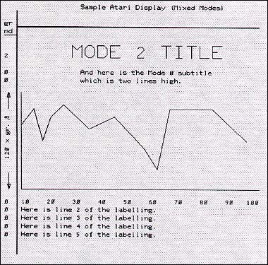
Remember the graph we wanted to create? First, we would stack a graphics 2 display block (the title) on top of two graphics O display blocks (the subtitle) on top of a bunch of graphics 8 display blocks, on top of the graph itself (see Figure 10.) It saves a lot of time to mix graphics modes and not have to go through all the work of plotting your characters in high resolution dots.
Let's follow ANTIC through the display refresh process. We will use our earlier example, the word READY on the screen in graphics 0, in the upper left hand corner.
|
| Figure 10. |
ANTIC has an instruction in its display list which keeps it waiting until the time rolls around for a new screen refresh (every sixtieth of a second). Once this occurs, ANTIC starts work. It needs to know what to put on the very first scan line. It looks to the display list for instructions. In our example, a graphics 0 display block is first. Mode 0 has 40 characters per display block, and it takes 8 scan lines to plot the block. ANTIC turns off the 6502 and grabs 40 bytes from the start of display memory, which are the numeric representations of "READY" and 35 spaces. ANTIC knows that since this is a character mode, these 40 bytes actually represent shapes stored in a shape table, so it goes to the shape table and finds all of their shapes. Over the next eight scan lines, ANTIC plots the READY as we learned in the previous chapter. It consults the display list again for what to do with the next display block, then grabs another 40 bytes from display memory using the Graphics 0 display block, right below the first 40, and plots another line of graphics 0 characters, and continues. After 24 display blocks, the display list tells ANTIC to stop and wait for the next refresh. The 6502 is turned back on again. In graphics 0, the 6502 is turned off about 30% of the time. In graphics 8, it is turned off about 60% of the time. One way to speed up calculations on the Atari is to turn off the display completely.
If we were in graphics 8, ANTIC would have to look to the display list 192 times, and find a graphics 8 instruction that same number of times. Now if the display list tells ANTIC to first plot a mode 2 row of characters, then two mode 0 rows, then a bunch of graphics 8 blocks, it will do that. This is how we mix graphics modes.
Clearly, you have to map out your displays in advance and also map out your display memory. Since display memory is used by ANTIC as a result of plotting display blocks of data, the memory must have the exact amount of data needed stacked in the same way as the display blocks.
Go to the sample graph. A line of graphics 2 characters takes up 20 bytes of memory. That is because only 20 characters (double wide) fit on one line in graphics 2. Since this is the first display block, these bytes must be at the start of display memory, where ANTIC will start looking for data for that mode 2 line. ANTIC plots them, and while doing so, moves forward 20 bytes in memory. Next it needs 40 bytes for data for the first of two graphics 0 display blocks. That 40 bytes must immediately follow the 20 bytes of mode 2 data in memory, because that is where ANTIC will be looking for them. Next, another mode 0 line (40 more bytes), then a mode 8 line. The mode 8 line uses 40 bytes per display block (320 points, with 8 points stored per byte, is 40 bytes), bit mapped rather than character addressed. The data following the second mode 0 line must be bit mapped format, ready for graphics 0 display.
ANTIC has no idea where you want bit mapped or character addressed data to start and end other than where it is in display memory when ANTIC needs more data. You control that through the display list. If you store 41 bytes of data for a mode 0 line, it will not wrap around. ANTIC will just use that extra byte as the first data byte for the next display block and could interpret it in either graphics or character mode, depending on the display list.
Just for practice, and as an example, let's lay out a sample display list and display memory, which follows from the display list's needs, for our graph.
We design our displays around the 192 available scan lines. We will mix graphics modes, but must make the total number of scan lines used come out to exactly 192.
Here is how we allocate the 192 scan lines:
16 X 1 = 16 lines in graphics 2 for our title.
8 X 2 = 16 lines in graphics 0 for our subtitle.
120 X 1 = 120 lines in graphics 8 for the actual graph.
5 X 8 = 40 lines in graphics 0 for the labels.
This gives us a total of 192 scan lines.
There is no great penalty if we do not come out exactly at 192 scan lines. If we have a few less, the display just will not reach to the bottom of the screen. If we have a few more, we will get some bizarre displays (you may want to try this out later on). Going past 192 can result in weird things happening, as ANTIC will keep sending information after it reaches the end of the screen.
We have allocated 192 scan lines in 120 display blocks. Next we will allocate display memory. This is done by adding up the individual display block requirements.
20 bytes X 1 line = 20 bytes for the first block in graphics 2.
40 bytes X 2 lines = 80 bytes for the next two blocks in graphics 0.
40 bytes X 120 lines = 4800 bytes for the next 120 blocks in graphics 8.
40 bytes X 5 lines = 200 bytes for the last five blocks in graphics 0.
This gives us a total of 5100 bytes for display memory.
To get our graph on the screen, we set up display memory with the needed data, character addressed for modes 0 and 2 and bit mapped for the mode 8 blocks, then set up the display list with its 120 display block instructions, and finally tell ANTIC to get going. It will, and the display will pop up on the TV. A quick review of the paper and pencil process:
1. Design your display as display blocks.
2. Map out the display list from those blocks.
3. Map out display memory from the display list.
It is much easier to plot a title in large letters using graphics mode 2, where you just have to put the right 20 bytes of data into display memory and put in a mode 2 display list instruction, than to construct the letters out of individual high-resolution dots. The Atari will do all the constructing for you, and save you a lot of time. Since programmer time is becoming the most expensive factor in owning a computer, this sort of time saving is very important.
We are going to need some tables on how many bytes the various graphics modes consume. We will also have to look at how color is stored in the Atari so you will know how display memory is actually formatted, while also understanding the idea of bit mapped memory. We will then start examining and modifying display lists to get some nice effects. If you can, have an Atari available to try out the examples.
Table of Contents
Previous Section: Dot Graphics Line
Next Section: More Memory Secrets