The light pen you built in Chapter 6 is a type of light sensor-it detects light from the computer's screen and sends out an appropriate signal. But what if you want to be able to tell whether it's dark outside, or whether somebody opened your closet door (letting light inside)? Or perhaps you want to build an electronic timer that starts and stops timing when a beam of light is broken? To detect different levels of light, you need a slightly more complex sensor.
This chapter will show you how to build and use a variable digital light sensor. This sensor provides the computer with either a high (1) or low (0) digital signal. When the light sensor is adjusted for a certain level of light, the computer receives a logic low (0) signal as long as this level of light, or more, is maintained. However, if the level of light falls below this setting, the computer gets a logic high (1) signal from the sensor. This type of sensor is useful for applications such as light beam timers and counters, two applications which will be demonstrated here as well.
To build the digital light sensor, you need these parts:

|
These steps will take you through the process of building your digital light sensor: |
||||||||||||||||||||||||||||||||||||
|
1. Cut three pieces of solid copper wire and
remove about 1/4 inch of insulation from each end. 2. Connect one wire each to pins 1, 7, and 8 of the 9-pin plug. 3. Connect the wire from pin 8 to location X1 of the solderless breadboard. 4. Connect the wire from pin 7 to location Y1. 5. Connect the wire from pin 1 to location F5. 6. Plug the 3900 op amp IC into the solderless breadboard so that pin 1 goes to point E15, and pin 8 goes to point F9. 7. Cut two pieces of solid copper wire about 2 inches long and remove about 1/4 inch of insulation from each end. Solder one wire to an out-side lead of the potentiometer. Solder the other wire to the middle lead of the potentiometer. 8. The wire from the outside lead connects to point X22 of the solderless breadboard. The wire from the potentiometer's middle lead connects to point A22. 9. Cut two pieces of stranded copper wire about 12 inches long and remove about 1/4 inch of insulation from each end. Solder one wire to the emitter of the phototransistor and the other wire to the collector. 10. The wire from the collector plugs into point Y22 of the solderless breadboard, while the wire from the emitter inserts into point J22. 11. Insert the resistors as follows on the solderless breadboard:
12. Connect five solid copper wire jumpers on the solderless breadboard as follows:
|
||||||||||||||||||||||||||||||||||||
Inside the Sensor
The phototransistor in this circuit acts as a switch. It's in series
with the 500K potentiometer. When light strikes the light-sensitive surface,
current will flow through the emitter-collector junction. The sensitivity
is set by adjusting the 500K ohm potentiometer in series with the phototransistor.
The operational amplifier's (op amp) inverting input is connected between
the potentiometer and the phototransistor. The voltage at the op amp's input
is determined by the resistances of the potentiometer and phototransistor.
The op amp is set up using the 10K ohm and 100K
ohm resistors so that when the input voltage is a certain level, its output
goes to the logic low level. The output of the op amp is connected to pin
1 of the control port through a 1K ohm resistor.

|
The phototransistor must be set for the desired
level of light. This is done by aiming the light-sensitive part of the phototransistor
at a light source, then adjusting the potentiometer for triggering at the
desired light level. Program 7-1 provides the necessary lines for testing
and adjusting this circuit. Adjust the potentiometer so that the output to the computer turns logic low. Once this is done, if the phototransistor receives less light, the input voltage of the op amp no longer will be the correct voltage to force its output low. As a result, pin 1 of the 9-pin plug returns to its normal logic high level. Putting It to Use |
||||||||||||||||||||||||||||||||||||
|
|
To use the light sensor, first turn off your computer.
Insert the 9-pin plug into port 2 of the Commodore 64 or 128 (there's only
one port on the VIC), or into port 1 of any Atari computer. Turn your computer
back on, type in, and run the version of Program 7-1 for your machine. For
this demonstration, the sensor is set to the lighting in the room, so make
sure that the light-sensitive portion of the phototransistor is uncovered
and facing up. Program 7-1-Commodore 64/128 JE 10 IFPEEK(56320)AND(2↑0)THEN20 XR 15 PRINT"{CLR}LIGHT IS ON":GOTO10 EP 20 PRINT"{CLR}LIGHT IS OFF":GOTO10 Program 7-1-VIC-20 QD 10 IF(PEEK(37151) AND 4)THEN PRINT " {CLR}LIGHT IS OFF" AS 20 IF(PEEK(37151) AND 4)=OTHEN PRINT {SPACE}"{CLR}LIGHT IS ON" SB 30 GOTO10 Program 7-1-Atari 10 IF STICK(0)=15 THEN PRINT "OFF" 20 IF STICK(0)=14 THEN PRINT "ON " 30 GOTO 10
Download (Saved BASIC)
When you run the program, a column of messages
should appear on the screen. Either the message LIGHT IS ON or LIGHT IS OFF
will be displayed. |
||||||||||||||||||||||||||||||||||||
|
|
Adjust the setting of the potentiometer by turning
its shaft. Doing this controls the sensitivity of the light sensor. You should
find a point as you turn the potentiometer shaft where the messages in the
column change from LIGHT IS OFF to LIGHT IS ON. In order to set the light
sensor to detect the light in the room, leave the potentiometer set at the
point where the messages just change from LIGHT IS OFF to LIGHT IS ON. Just as with a joystick, programs can check the control port for the light sensor's signal. All that's necessary is to PEEK the appropriate register, or use the STICK command in the case of the Atari, then check the bit (corresponding to pin 1, in this case) for a 1 or 0. A Digital Light Beam Timer This circuit, quite similar to the light sensor, can be used as a timer circuit for slot cars, or for any application involving measuring time over a distance. This project is essentially the same as the digital light sensor circuit you just completed. The following parts are required: |
||||||||||||||||||||||||||||||||||||
|
|
|
||||||||||||||||||||||||||||||||||||
|
|
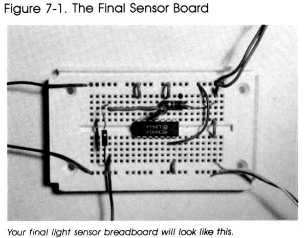
Construct the circuit as you did for the digital light
sensor, but position the infrared emitting diode and the infrared detecting
diode so that the emitting surface and detecting surface face each other.
Tests indicate that the maximum usable distance between these diode pairs
(the two parts come in one package, listed as Radio Shack part number 276-142)
is less than one foot. Connect the infrared emitter's anode to the y line on the solderless breadboard, and the cathode to the x line. Use the appropriate version of Program 7-1 to adjust and focus the diodes so that the circuit triggers when the beam of light from the emitter is broken, not when ambient room light is interrupted. The light in the infrared is invisible to the naked eye. You'll see no indication that the diode is turned on. Be sure you've in-stalled it correctly in the circuit. |
|
|
When you've tested the circuit and are satisfied
that it's functioning properly, type in and run Pro-gram 7-2. Adjust the
potentiometer as you did with the digital light sensor, then press the X
key to continue the program. Start the timer by breaking the beam between the infrared emitting and infrared detecting diodes. When the beam is broken a second time, the elapsed time is displayed and the timer stops. Press the X key to reset the timer and run the program again. This circuit could be useful as a burglar alarm, one that detects when an object or intruder breaks the beam of infrared light. Program 7-2-Commodore 64/128 DX 110 REM TIMER PROGRAM MH 120 PRINT"{CLR}ADJUST THE INFRARED BEAM AND THE" FA 130 PRINT"POTENTIOMETER UNTIL THE MESSAGE JUST" GQ 140 PRINT"CHANGES FROM OFF TO ON" MG 150 PRINT:PRINT"PRESS X TO CONTINUE {DOWN}" AQ 160 A$=CHR$(145)+CHR$(145) PM 165 A=PEEK(56320) JM 170 IF (A AND 1) THEN PRINT "LIGHT IS OFF" GE 175 IF (A AND 1)=0 THEN PRINT "LIGHT {SPACE}IS ON " KE 180 GET B$ BQ 190 IF B$="X"THENGOTO220 DS 200 PRINTA$ AD 210 GOTO 165 HD 220 PRINT"{CLR}BREAK BEAM TO START TIMER" QX 230 IF (PEEK(56320) AND 1)=0 THEN 230 DF 240 TI$="000000":PRINT"{CLR}TIMER STARTED" MD 250 IF (PEEK(56320) AND 1) THEN 250 KH 260 IF (PEEK(56320) AND 1)=0 THEN 260 RC 270 PRINT"TIME IS";TI/60;"SECONDS" XH 280 PRINT"{DOWN}PRESS X TO RESET TIMER" DG 290 GETB$:IFB$=""THEN290 CD 300 IFB$="X"THEN220 MK 310 GOTO290 Program 7-2-VIC-20 SH 10 PRINT"{CLR}ADJUST THE INFRARED {3 SPACES}BEAM AND THE CIRCUIT QS 20 PRINT"UNTIL THE MESSAGE JUST" SR 30 PRINT"CHANGES FROM OFF TO ON" KQ 40 PRINT:PRINT"PRESS X TO CONTINUE" GM 50 A$=CHR$(145) PB 60 A=PEEK(37137) AE 70 IF (A AND 4) THEN PRINT "LIGHT IS {SPACE}OFF" PQ 80 IF (A AND 4)=0 THEN PRINT "LIGHT I S ON " XA 90 GET B$ MH 100 IF B$="X"THEN130 QB 110 PRINTA$A$ SQ 120 GOTO60 PH 130 PRINT"(CLR}BREAK BEAM TO START" RP 140 IF (PEEK(37137)AND4)=0 THEN140 KS 150 TI$="000000" RX 160 IF (PEEK(37137) AND 4) THEN160 JD 170 IF (PEEK(37137) AND 4)= 0 THEN170 MQ 180 PRINT"TIME IS";TI/60;"SECONDS" HD 190 PRINT"PRESS X TO RESET TIMER" XA 200 GETG$:IFG$=""THEN200 QX 210 GOTO130 Program 7-2-Atari AP 110 REM TIMER PROGRAM KP 120 PRINT "TURN ON FLASHLIGHT AND ADJUST THE" LF 130 PRINT "POTENTIOMETER TILL THE MESSAGE JUST" KO 140 PRINT "CHANGES FROM OFF TO ON FE 150 PRINT "PRESS X TO CONTINUE" GH 155 FOR J=1 TO 2500:NEXT J KE 170 IF STICK(0)=15 THEN PRINT "OFF" 6K 175 IF STICK(0)=14 THEN PRINT "ON” MB 180 REM CHECK IF X KEY PRESSED KI 190 IF PEEK(764)=22 THEN 215 GE 210 GOTO 170 BG 212 REM CLEAR OUT PREVIOUS KEYSTROKE DA 215 POKE 764,255 JB 220 PRINT "BREAK BEAM TO START TIMER" IJ 230 IF STICK(0)=14 THEN 230 CA 240 POKE 18,0:POKE 19,0:POKE 20,0 IO 250 IF STICK(0)=15 THEN 250 IP 260 IF STICK(0)=14 THEN 260 BG 270 PRINT "TIME IS ";((PEEK(18)*255*255)+(PEEK(19)*255)+(PEEK(20)))/60;" SECONDS"
Download (Saved BASIC)
For something a little different, modify Program 7-2 to count (COUNT
= COUNT + 1) every time the beam is interrupted. |
Return to Table of Contents | Previous Chapter | Next Chapter