So far, all the projects you've completed have been sensors-devices that transfer information about the outside world into your computer. But your computer can also be used to control outside devices through electronic signals.
While exploring the control port, you saw how information in the form of electronic on/off signals can be sent to your computer using the data (I/O) lines. These same wires can also be used by your computer to send digital signals out. Whether your computer is using the data lines for input or output, two registers are involved.
The first register, called the data port, contains the actual data being transferred. The signal on each data line corresponds with a bit stored at this location. When receiving data, your program simply checks the bit which corresponds to the affected I/O line. Suppose you wish to see whether pin 1 of control port 1 is set low, as it is if the joystick is pushed to the up position. For the Commodore 64/128, you could use the following statement:
10 IF (PEEK(56321) AND 2↑0)=0 THEN PRINT "YES"
On the VIC-20, you'd use this instead:
10 IF (PEEK(37137) AND 2↑0)=0 THEN PRINT "YES"
Since the zero bit in the memory location (the register) corresponds with pin 1 (the I/O line), the word YES is printed if this bit is set low.
When outputting data, your program must alter the contents of the data port and set the port for output. Suppose you want to set pin 1 of port 2 to output a logic high signal. To do this, your program must set bit 0 in the data direction register to a 1 for output:
For Commodore 64/128:
10 POKE 56321,PEEK(56321)OR(2↑0)
For Commodore VIC-20:
10 POKE 37137,PEEK(37137)OR(2↑0)
Each I/O pin of the control port has a corresponding bit in the data direction register. When a control port pin is to be used for input, its bit in this register must be set low. Setting a data direction register bit high, on the other hand, makes its corresponding control port pin an ouput line. The data lines are normally set for input-that's why you could ignore this register when you were first exploring the control port.
However, when you want the computer to output signals, this register must first be set. The data . direction registers are located at memory locations 56322 ($DC02 in hexadecimal) for joystick port 2 and 56323 ($DC03) for joystick port 1 on the Commodore 64 and 128, and location 37139 ($9113) for the VIC-20.
The Atari Computers
The Atari computers are a little different when it comes to sending and receiving data. A data register and data direction register are still used, but unlike the Commodore computers, the Atari's registers are both at the same memory location.
Though you previously used the BASIC STICK command to check input to the control port, you can also use one of the computer's registers directly to obtain the same information. Bits 0-3 of memory location 54016 ($D300) correspond to pins 1-4 of control port 1, respectively, while bits 4-7 correspond to pins 1-4 of control port 2. By PEEKing this memory location, you can see what data has been input through the control ports. This same register is used to send information out of the computer using the control ports' lines. This is done by POKEing values into the register to set the bits corresponding to the control ports' pins either high or low. Memory location 54016 is used as a data register and contains the information being either sent or received.
Memory location 54016 acts as a data register, accepting incoming data, as long as bit 2 of memory location 54018 ($D302) is set to 0. If bit 2 of memory location 54018 is set to 1, location 54016 acts as a data direction register. Outgoing data can now be sent. The control ports' pins are set as either input or output lines, depending on whether their corresponding bits of the data direction register are 0's or 1's. You can set memory location 54016 to be the data direction register by
POKE 54018,48
and return it to acting as a data register with
POKE 54018,52

|
Note: With Atari BASIC, you cannot mask or force
bits using ANDs and ORs in POKE statements as with Commodore computers. To
set an individual bit in a memory location high, you can POKE the value directly,
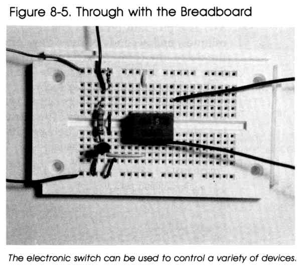
such as POKE location, 2^bit where location is the memory address you wish to change and bit is the bit within that address that you wish to set. For example, to set bit 2 of location 54016, you would use POKE 54016,4 Without AND and OR, there's no easy way to change a single bit without affecting the current settings of the other bits in the location. For example, if location 54016 already has bits 6 and 7 set (corresponding to a value of 192 in the location) and you wish to set bit 3 without affecting the others, then the value you must POKE into 54016 is 200, 192 + (2^3). Using a Computer's Output Signals How can an on/off signal from the computer control events in the outside world? An electronic circuit is required to take the digital signals that the computer outputs and perform some useful task. One example of this type of circuit is the electronic switch you'll make. It allows your computer to switch things on and off under the control of a computer program. Building the Electronic Switch You'll need these parts to construct your electronic switch: |
||||||||||||||||||||||||||||||

|
Follow these steps to build your electronic switch if you have a Commodore computer (the steps are identical for the Atari, though some additional steps are listed below). |
||||||||||||||||||||||||||||||
|
1. The first step in constructing the electronic
switch is to wire the 9-pin plug. Cut three pieces of wire about four inches
long and remove about 1/4 inch of the insulation from each end. 2. Solder wires to pins 1, 7, and 8. 3. Connect the three wires as follows: The wire from pin 8, the ground wire, connects to point Y1 on the solderless breadboard. The +5-volt wire from pin 7 connects to point X1 of the solderless breadboard. The data line from pin 1 connects to location B4 on the board (except for the Atari version-see below). 4. Connect the 2.2K ohm resistor between points A4 and F4 on the solderless breadboard. 5. Mount the 2N2222 transistor so that its base inserts into point H4, its emitter into point H3, and its collector into point H5. 
|
||||||||||||||||||||||||||||||
|
|
6. The diode is connected so that its cathode lead
inserts into point X5 of the solderless breadboard and its anode lead connects
to point B5. (A band around one end of the diode is generally used to identify
the cathode lead.) 7. The SPDT relay is inserted so that its normally open and normally closed pins attach to points F9 and E9 respectively. The common pin connects to point E14. 8. The following jumper connections are required to complete the electronic switch. Wire From To 1 J3 Y3 2 J5 J10 3 E5 F5 4 X10 A10 Additional Steps for Atari Version Only |
||||||||||||||||||||||||||||||
|
|
9. Insert the 7400 IC into the solderless breadboard
so that its pins 1 and 8 go into plug points F16 and E22 respectively. 10. Insert the wire from pin 1 of the 9-pin plug into point J16 of the solderless breadboard. 11. Add the following jumper connections. Wire From To 5 X16 A16 6 J22 Y22 7 H16 G17 8 G18 G19 9 H19 G20 10 G21 B4 |
||||||||||||||||||||||||||||||
Switch Is On
The 9-pin plug connects to control port 1 of your computer. The circuit
draws its power from the computer's power supply through the wires from pins
7 and 8. The wire from pin 1 provides the circuit with a digital signal.
This signal can be set by the program to be either logic high or logic low.
Pin 1 of the control port is connected to the base
of the transistor through a current-limiting resistor. If the signal from
the computer is +5 volts (logic high), current flows from this pin through
the base of the transistor. This base current causes the transistor to act
as a closed switch between its emitter and collector leads. When the transistor
acts as a closed switch, current flows from the +5 volts of the power supply
through the coil of the relay to ground. The relay turns on due to this
coil current. The Atari version of the circuit uses two NAND gates as a
noninverting buffer. This buffer is required since the signal from the Atari's
control port is not sufficient to turn on the transistor. Refer to Chapter
10, "Digital Logic," for more on buffers and gates.
When a logic low signal (0 volts) is present at pin
1, no base current flows in the transistor. As a result, the transistor acts
as an open switch across its emitter and collector leads. Consequently,
the relay assumes its off position since no current flows through
its coil.
The relay is an electromechanical switch. The device
to be controlled is connected to the relay via its common, normally open
and normally closed terminals. The circuit which controls the device is
attached to the coil terminals of the relay.
When the relay is off, a metal lever bridges the gap
between its common and normally closed terminals. The coil of the relay
is part of an electromagnet. When current flows through this coil (to turn
the relay on), the electromagnet pulls the metal lever so that it bridges
the gap between the common and normally open terminals instead.
Many electric devices can be switched on and off by
this circuit. A description of using the circuit to turn on an LED appears
below. To use this circuit to control other devices, connect the devices
between points G9 and D14, the two points marked A in Figure 8-3. Other devices
should have their own power supply, such as a battery connected in series
with point G9 or D14 and the device itself. (You can see the connection from
the breadboard to a 6-volt battery in Figure 8-4.) Caution should be exercised
not to exceed the current rating of the SPDT DIP relay.
Using the Electronic
Switch-Flashing an LED
Here's one application for your electronic switch- a computer-controlled
LED. The computer program, with the aid of the electronic switch, turns
on the LED after a specified time delay. For this application, you'll need
to connect two jumper wires and the LED.
|
|
1. Connect a wire between points X8 and G9 on
your solderless breadboard. 2. Also connect a jumper between points Y15 and J15. 3. Plug the cathode of the LED into point D15 and its anode into D14. First of all, insert the 9-pin plug of the electronic switch circuit into control port 1 of your computer. Next, turn on your computer. |

|
Enter and run the appropriate version of Program
8-1. The program prompts you to enter the hours, minutes, and seconds of
the delay. After you enter the delay, the computer will wait that length
of time before turning on the LED-the LED will remain on for only about
five seconds. To turn on the LED, the program sets pin 1 of the control port to logic low. This turns off the relay, closing the connection between its common and normally closed terminals. Program 8-1-Commodore 64/128 KR 10 PRINT"ENTER HOURS"; BK 20 INPUTA SS 30 PRINT"ENTER MINUTES"; DP 40 INPUTB SG 50 PRINT"ENTER SECONDS"; RR 60 INPUTC GP 70 D=(A*216000)+(B*3600)+(C*60) QE 80 REM START TIMER QR 90 TI$="000000" RM 100 IFTI>DTHEN130 QH 110 GOTO100 KX 120 REM SET DATA LINES FOR OUTPUT JJ 130 POKE 56323,PEEK(56323)OR(2↑0) DH 140 REM SET DATA LINES TO LOGIC LOW TO TURN ON BUZZER CF 150 POKE 56321,PEEK(56321)ANDNOT(2↑0) FX 160 REM KEEP BUZZER ON FOR FIVE SECONDS AA 170 TI$="000000" DK 180 IF TI>300 THEN210 HB 190 GOTO180 SQ 200 REM SET DATA LINE TO LOGIC HIGH TO TURN OFF BUZZER XJ 210 POKE 56321,PEEK(56321)OR(2↑0) FC 220 REM RESET DATA LINE FOR INPUT QQ 230 POKE 56323,PEEK(56323)ANDNOT(2↑0) Program 8-1-VIC-20 KR 10 PRINT"ENTER HOURS"; BK 20 INPUTA SS 30 PRINT"ENTER MINUTES"; DP 40 INPUTB SG 50 PRINT"ENTER SECONDS"; RR 60 INPUTC GP 70 D=(A*216000)+(B*3600)+(C*60) QE 80 REM START TIMER QR 90 TI$="000000" RM 100 IFTI>DTHEN130 QH 110 GOTO100 KX 120 REM SET DATA LINES FOR OUTPUT BM 130 POKE 37139,PEEK(37139)OR(2↑2) DH 140 REM SET DATA LINES TO LOGIC LOW TO TURN ON BUZZER BD 150 POKE 37137,PEEK(37137)ANDNOT(2↑2) FX 160 REM KEEP BUZZER ON FOR FIVE SECON DS AA 170 TI$="000000" DK 180 IF TI>300 THEN210 HB 190 GOTO180 SQ 200 REM SET DATA LINE TO LOGIC HIGH TO TURN OFF BUZZER GM 210 POKE 37137,PEEK(37137)OR(2↑2) FC 220 REM RESET DATA LINE FOR INPUT RM 230 POKE 37139,PEEK(37139)ANDNOT(2↑2) Program 8-1-Atari IG 100 REM TIME BUZZER KO 120 PRINT "ENTER HOURS"; GF 130 INPUT A EE 140 PRINT "ENTER MINUTES"; GI 150 INPUT B OA 160 PRINT "ENTER SECONDS"; GL 170 INPUT C PP 180 D=(A*216000)+(B*3600)+(C*60) OE 190 POKE 18,0:POKE 19,0:POKE 20,0 OJ 200 IF ((PEEK(18)*255*255)+(PEEK( 19)*255)+ (PEEK(20)))>D THEN 220 FO 210 GOTO 200 NF 215 REM SET DATA LINES FOR OUTPUT FN 220 POKE 54018,48 JA 225 POKE 54016,255 FJ 230 POKE 54018,52 NK 235 REM SET DATA LINES LOGIC LOW TO TURN ON BUZZER CB 240 POKE 54016,0 OF 245 POKE 18,0:POKE 19,0:POKE 20,0 EC 250 IF ((PEEK(18)*255*255)+(PEEK( 19)*255)+ (PEEK(20)))>300 THEN 270 GI 260 GOTO 250 MI 265 REM SET DATA LINES HIGH TO TURN OFF BUZZER JA 270 POKE 54016,255 AN 280 REM RESET DATA LINES FOR INPUT BE 290 POKE 54018,48 BO 300 POKE 54016,0 FI 310 POKE 54018,52
Download (Saved BASIC)
Other Applications |
|
|
Warning: If you're planning on using the switch
to turn on lights, a coffee pot, or any appliance connected to house line
voltage, remember that the relay must be rated to handle the current needed
by the appliance. Potentially lethal voltages will be present at the
relay. The relay should be housed in a container to prevent accidental
contact, and good electrical practices should be employed. For additional
safety, a buffer circuit should be employed to further isolate your computer
(and yourself) from high voltages. |
Return to Table of Contents | Previous Chapter | Next Chapter