SPECIAL CHIPS AND ROM
OK, we're now done with all the RAM locations. That leaves the ROM and the special chips, which covers the GTIA (or CTIA), POKEY, PIA, and ANTIC chips along with the OS ROM. We'll learn what each of the chips does as we come across it.
ROM, of course, stands for Read Only Memory, which means that you can't store values in it. You can't store values in the chips, either, but as you read through the following locations you'll notice that I tell you to POKE to them. What's going on here? When you POKE a value in a chip location, the chip will see the value and act accordingly, but won't store it anywhere. That means that if you POKE some location with a value and then PEEK that location, you won't necessarily get the value you POKEd. It's OK though, because the chip knows what you were trying to do and acts as though the value is in the location. Confused? Just remember that POKE works, but PEEK won't always.
Because the value you POKE is different from the value you PEEK, a lot of the ROM locations have different meanings depending on whether you're PEEKing or POKEing. In such a case, I'll give you an explanation of each.
Now that you think you understand, one more thing to try and trip you up. You can't POKE to the OS ROM at all. Well, you can if you want to, but nothing will happen.
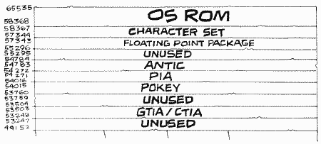
Let's do a little memory mathematics. First of all, let's start with a 48K Atari. It's actually a 64K Atari. Where's the other 16K? The OS ROM takes up 10K, so that leaves 6K unaccounted for. 1.25K is taken up by the chips mentioned, so we're down to 4.75K. Would you believe that 4.75K of memory is unused? Well, you should, because it is. Unfortunately, it's all in ROM and therefore you can't use it either. 4K of it is right here, at locations 49152 through 53247 ($C000 through $CFFF). The other .75K, which, by the way, is equal to three pages since a page is .25K, is found amongst the chips at locations 53504 through 53759 ($D100 through $D1FF) and 54784 through 55295 ($D600 through $D7FF). Anyway, that means we have 48K to program with, right? Nope. The BASIC cartridge takes up 8K, as we saw, so we're down to 40K. We already saw that the first 1792 bytes (or 1.75K) are used by BASIC, the OS, and the floating point package, and then on top of that there's screen memory and the memory that the FMS and DOS use if you're using a disk drive. That leaves anywhere from about 37K down to 29K or less! Oh well, I guess even computers can lose their memories (OK, OK, I'm sorry).
GTIA OR CTIA
Time to answer a question that may have been nagging at a lot of you. What's the difference between GTIA and CTIA? And for that matter, what is a CTIA/GTIA? Let's start with the second question first. Way back when the Atari computers were still being designed, they had nicknames. The 400 was called Candy, and the 800 Colleen. So much for trivia. Both Colleen and Candy needed some way of talking to the television set, so a Television Interface Adapter chip was designed. That's where you get the name CTIA from (Colleen/Candy Television Interface Adapter). The CTIA chip gets information from ANTIC and uses it to tell the television set what to do. So much for that.
When the CTIA was originally designed, it was supposed to support 12 graphics modes (0 to 11). Unfortunately, the last 3 modes couldn't be implemented in time to make the production deadline. Rather than hold off releasing the computers, Atari decided to put them out without those three modes and add the modes later. So that's why the early computers don't support modes 9, 10, and 11. After the first batch of CTIAs ran out, Atari starting putting in chips that had the extra 3 modes, for some reason calling them GTIAs, with the "G" standing for George. Maybe George was the guy who finally figured out how to get the last modes to work, I don't know. In any case, that's the difference between CTIA and GTIA. Oh, GTIA also corrects another problem that CTIA had. It seems that you couldn't line up players and playfield exactly (they were off by half a color clock). To correct this problem, GTIA shifts the playfield by half a color clock. Unfortunately, this means that colors obtained by artifacting (see COLOR1 at location 709 [$02C5]) will be the opposite of what they're supposed to be. If you're writing a program that uses artifacting, and you want to make sure that the colors come out right on both the CTIA and the GTIA, there is a program in Appendix Four that you can use to check which chip is present. Once you know that, you can shift everything over one column if necessary.
The C/GTIA takes up locations 53248 through 53505 ($D000 through $D0FF).
You're now about to enter player/missile territory. That's right, C/GTIA also takes care of player/missile graphics. Since this is such a detailed and popular subject, there is a whole appendix in the back of the book devoted entirely to telling you how to program player/missile graphics. Therefore, the descriptions here will be short and sweet.
Please see the appendix if you don't know what's going on.
HPOSP0 (POKE) and M0PF (PEEK)
53248 D000
(POKE) HPOSP0 specifies the horizontal location of player zero, and can range from 0 to 227. Note that some of these positions will be off the edge of the screen, so experiment to see what values can be seen on your screen. For most television sets, anything between 48 and 208 will be visible.
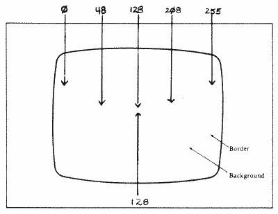
Because this location is in one of the chips, you will not be able to PEEK here to find out the current position of the player (see the following for what you get when you PEEK). That means that you should keep track of the position in a separate variable.
(PEEK) M0PF is a collision register. Collision registers are used to tell who's collided with whom on the screen (in other words, who's sharing the same pixels with whom). They can be very useful in games and other applications. Note that the collision registers do not work properly in GTIA modes nine through eleven. You should also check HITCLR at location 53278.
M0PF tells you what part of the playfield missile zero has collided with (the background is not considered part of the playfield here). Its bits have the meanings in Figure 30.
| -------1 | (1) |
means a collision with playfield zero. |
| ------1- | (2) |
means a collision with playfield one. |
| -----1-- | (3) |
means a collision with playfield two. |
| ----1--- | (4) |
means a collision with playfield three. |
FIGURE 30. M0PF bit chart
HPOSP1 (POKE) and M1PF (PEEK)
53249 D001
(POKE) HPOSP1 specifies the horizontal position of player one.
(PEEK) M1PF is the collision register for missile one/playfield collisions.
HPOSP2 (POKE) and M2PF (PEEK)
53250 D002
(POKE) HPOSP2 specifies the horizontal position of player two.
(PEEK) M2PF is the collision register for missile two/playfield collisions.
HPOSP3 (POKE) and M3PF (PEEK)
53251 D003
(POKE) HPOSP3 specifies the horizontal position of player three.
(PEEK) M3PF is the collision register for missile three/playfield collisions.
HPOSM0 (POKE) and P0PF (PEEK)
53252 D004
(POKE) HPOSM0 specifies the horizontal position of missile zero (missiles move just like players).
(PEEK) P0PF is the collision register for player zero/playfield collisions. It works just like the missile/playfield collision registers.

HPOSM1 (POKE) and P1PF (PEEK)
53253 D005
(POKE) HPOSM1 specifies the horizontal position of missile one.
(PEEK) P1PF is the collision register for player one/playfield collisions.
HPOSM2 (POKE) and P2PF (PEEK)
53254 D006
(POKE) HPOSM2 specifies the horizontal position of missile two.
(PEEK) P2PF is the collision register for player two/playfield collisions.
HPOSM3 (POKE) and P3PF (PEEK)
53255 D007
(POKE) HPOSM3 specifies the horizontal position of missile three.
(PEEK) P3PF is the collision register for player three/playfield collisions.
SIZEP0 (POKE) and M0PL (PEEK)
53256 D008
(POKE) SIZEP0. You can set the size of each player (in terms of width) to one of three possibilities, each of which is twice as wide as the one before it. A value of zero or two in this or the next three locations specifics normal width, which is eight color clocks wide (the same width as a graphics mode two character). Similarly, a one specifies double width, and a three quadruple width.
A player is normally eight bits wide. Changing the width does not affect this but rather shows each bit two or four times in a row (for example, Figure 31).
Normal Width (zero)
For Player 0: POKE 53256,0
For Player 0: POKE 53256,0
10011001
10111101
11111111
10111101
10011001
10111101
11111111
10111101
10011001
#
## #
# #### #
########
# #### #
# ## #
# #### #
########
# #### #
# ## #
FIGURE 31 (partial).
Changing player widths
Two things to note here. First, the height of the player is not changed, and second, each player can be set separately.
Double
Width (one)
POKE 53256,1
1100001111000011
1100111111110011
1111111111111111
1100111111110011
1100001111000011
## #### ##
## ######## ##
################
## ######## ##
## #### ##
POKE 53256,1
1100001111000011
1100111111110011
1111111111111111
1100111111110011
1100001111000011
## #### ##
## ######## ##
################
## ######## ##
## #### ##
Quadruple
Width (three)
POKE 53256,3
11110000000011111111000000001111
11110000111111111111111100001111
11111111111111111111111111111111
11110000111111111111111100001111
11110000000011111111000000001111
#### ######## ####
#### ################ ####
################################
#### ################ ####
#### ######## ####
FIGURE 31 (continued). Changing player widths
(PEEK) M0PL is the collision register for missile zero/player collisions. Its bits have the meanings in Figure 32.
| -------1 | (1) |
means a collision with player zero. |
| ------1- | (2) |
means a collision with player one. |
| -----1-- | (3) |
means a collision with player two. |
| ----1--- | (4) |
means a collision with player three. |
FIGURE 32. M0PL bit chart
Because of the way player/missile graphics is designed, there is no way to detect a collision between two missiles.
SIZEP1 (POKE) and M1PL (PEEK)
53257 D009
(POKE) SIZEP1 specifies the width of player one.
(PEEK) M1PL is the collision register for missile one/player collisions.
SIZEP2 (POKE) and M2PL (PEEK)
53258 D00A
(POKE) SIZEP2 specifies the width of player two.
(PEEK) M2PL is the collision register for missile two/player collisions.
SIZEP3 (POKE) and M3PL (PEEK)
53259 D00B
(POKE) SIZEP3 specifies the width of player three.
(PEEK) M3PL is the collision register for missile three/player collisions.
SIZEM (POKE) and P0PL (PEEK)
53260 D00C
(POKE) The missiles only have one location that is used to specify their widths, and SIZEM is it. This is how the bits are used (Figure 33).
| ------00 or ------10 ------01 ------11 |
(0) (2) (1) (3) |
for normal width missile zero. for double width missile zero. for quadruple width missile zero |
| ----00-- or ----10-- ----01-- ----11-- |
(0) (8) (4) (12) |
for normal width missile one. for double width missile one. for quadruple width missile one |
| --00---- or --10---- --01---- --11---- |
(0) (32) (16) (48) |
for normal width missile two. for double width missile two. for quadruple width missile two. |
| 00------ or 10------ 01------ 11------ |
(0) (128) (64) (192) |
for normal width missile three. for double width missile three. for quadruple width missile three. |
FIGURE 33. SIZEM bit chart
(PEEK) P0PL. Now it's time for player-to-player collision registers. P0PL has exactly the same meaning as M0PL, except it detects player zero/player collisions rather than missile zero/player collisions. Note that a player will never collide with itself.
GRAFP0 (POKE) and P1PL (PEEK)
53261 D00D
(POKE) When G/CTIA is drawing the screen, it relies on the five GRAF registers (this one and the four following) to tell it what the players and missiles will look like (GRAF stands for "GRAFics register"). Everytime G/CTIA comes to a horizontal position on the screen where a player/missile is supposed to be, it looks at the corresponding register to see what to put on the screen. Now it's probably occurred to you that the GRAF registers are only one byte long. That means that unless someone puts new values in them every time a new line on the screen gets drawn, all the players and missiles will just look like a bunch of vertical lines. So who's going to do the changing? If you're adventurous (and good with machine language), you can do it yourself, but there's a much easier way. If we tell GRACTL (53277) and DMACTL (54272) to turn on DMA (Direct Memory Access) for players and missiles, then ANTIC will very thoughtfully keep changing the GRAF registers for us. All we have to do is put a description in memory of how we want the players and missiles to look. See PMBASE (54279) for information on how to do that.
If you want a quick way to create some kind of vertical border, use the GRAF registers without DMA. By POKEing a value of 255 into GRAFP0, for example, you can get a vertical band the height of the screen. Note, however, that you have to turn off DMA for all players.
(PEEK) P1PL is the collision register for player one/player collisions.
GRAFP1 (POKE) and P2PL (PEEK)
53262 D00E
(POKE) GRAFP1 is the graphics register for player one.
(PEEK) P2PL is the collision register for player two/player collisions.
GRAFP2 (POKE) and P3PL (PEEK)
53263 D00F
(POKE) GRAFP2 is the graphics register for player two.
(PEEK) P3PL is the collision register for player three/player collisions.
GRAFP3 (POKE) and TRIG0 (PEEK)
53264 D010
(POKE) GRAFP3 is the graphics register for player three.
(PEEK) Remember the STRIGs back at locations 644 through 647? Well, they were the shadow registers for the TRIGs, which work the same way. A zero means the joystick button is pressed (joystick zero in this case), a one means it isn't. With the TRIGs, you can make it so that if a button is pressed, TRIG will stay set to zero until you reset it. See GRACTL (53277) to find out how. Otherwise, TRIG will return to one as soon as the button is released.
For those of you who are hardware minded, the TRIGs read the value of pin six of the controller jacks.
GRAFM (POKE) and TRIG1 (PEEK)
53265 D011
(POKE) GRAFM is the graphics register for the missiles. Since missiles are only two bits wide, all four can fit into one register. The bits are assigned as in Figure 34.
| BIT |
7 |
6 |
|
5 |
|
4 |
|
3 |
|
2 |
|
1 |
|
0
|
|
| USE |
M3 |
|
M2 |
|
M1 |
|
M0 |
FIGURE 34. GRAFM bit chart
If all the missiles are in the same byte, how do you change one without affecting the others? It's not easy from BASIC. You have to somehow break the byte up into four parts, change the part you want, and then put it back together. See the appendix on player/missile graphics for a routine to help you do this. In machine language, all you have to do is use AND to look at the bits you want and to clear them, and ORA to reset them. Don't forget that you can't PEEK GRAFM, so you'll have to keep track of its value in a separate variable (which is taken care of for you if you're using DMA). Again, see the appendix for more of an explanation.
(PEEK) TRIG1 is the value of joystick button one. It has a shadow register STRIG1 at location 645 ($285).
COLPM0 (POKE) and TRIG2 (PEEK)
53266 D012
(POKE) This specifies the color and brightness of player zero and missile zero. Sound familiar? That's because it has a shadow register called PCOLR0 at location 704. Look there for more information.
(PEEK) TRIG2 is the value of joystick button two. It has a shadow register STRIG2 at location 646 ($286).
COLPM1 (POKE) and TRIG3 (PEEK)
53267 D013
(POKE) COLPM1 is the color and brightness of player one and missile one. It has a shadow register PCOLR1 at location 705.
(PEEK) TRIG3 is the value of joystick button three. It has a shadow register STRIG3 at location 647 ($287).
COLPM2 (POKE) and PAL (PEEK)
53268 D014
(POKE) COLPM2 is the color and brightness of player two and missile two. It has a shadow register PCOLR2 at location 706.
(PEEK) It would be too easy to make fun of this location, so I'll spare you. What a PAL, huh? There are three types of television standards around the world: PAL, NTSC, and SECAM (a television standard just specifies how the television should work). PAL is used in Europe, NTSC here in North America, and SECAM in France, Russia, and parts of Africa. Atari has two different versions of the computer, one for PAL and one for NTSC (so we'll ignore SECAM). What's the difference? The PAL Ataris run about 25 percent faster than the NTSC Ataris. Also, PAL televisions have more scan lines than NTSC ones, which means that VBLANK occurs approximately every fiftieth of a second rather than every sixtieth.

"So what?" you're saying (I can hear you). Actually, unless you're programming for a PAL Atari, nothing I just said will be of any concern to you. If you are programming for a PAL, however, you should be aware of the differences.
I almost forgot. PAL (the memory location) is used to determine what kind of Atari you have. The bits have the following meaning:
----000-
(0) means that the computer is set up for PAL.
----111- (14) means that it's set up for NTSC.
----111- (14) means that it's set up for NTSC.
Make sure you only check bits two, three, and four (i.e., on an NTSC computer, PEEK(53268) won't necessarily give you 14; it might give you 15).
COLPM3 (POKE only)
53269 D015
COLPM3 is the color and brightness of player three and missile three. It has a shadow register PCOLR3 at location 707.
COLPF0 (POKE only)
53270 D016
OK, we're out of the player/missile color registers and into the playfield color registers. See the shadows at locations 708 through 712 for more information.
COLPF0 is the color and brightness of playfield zero and has a shadow register COLOR0 at location 708.
COLPF1 (POKE only)
53271 D017
COLPF1 is the color and brightness of playfield one and has a shadow register at location 709.
COLPF2 (POKE only)
53272 D018
COLPF2 is the color and brightness of playfield two and has a shadow register at location 710.
COLPF3 (POKE only)
53273 D019
COLPF3 is the color and brightness of playfield three and has a shadow register at location 711.
COLBK (POKE only)
53274 D01A
COLBK is the color and brightness of the background and has a shadow register at location 712.
PRIOR (POKE only)
53275 D01B
PRIOR is used to select the priorities of the various objects on the screen. What? Check its shadow register GPRIOR at location 623 for an explanation.
VDELAY (POKE only)
53276 D01C
As you'll find out later, at location DMACTL (54272), you can choose one- or two-line resolution for your players and missiles. If you choose two-line, however, you have to move things vertically two lines at a time rather than one. VDELAY can be used to move things down by one line. Its bits specify the object to be moved (Figure 35).
| -------1 | (1) |
means move missile zero down one. |
| ------1-
|
(2) |
means move missile one. |
| -----1-- | (4) |
means move missile two. |
| ----1--- | (8) |
means move missile three. |
| ---1---- | (16) |
means move player zero. |
| --1----- | (32) |
means move player one. |
| -1------ | (64) |
means move player two. |
| 1------- | (128) |
means move player three. |
FIGURE 35. VDELAY bit chart
To continuously move an object down, just repeat the following loop:
1. Set the
appropriate bit to one.
2. Move the shape data forward one byte in memory and set the bit back to zero.
3. Go to step 1.
2. Move the shape data forward one byte in memory and set the bit back to zero.
3. Go to step 1.
To continuously move it up:
1. Move the data
back one byte and set the appropriate bit to one.
2. Set the bit back to zero.
3. Go to step 1.
2. Set the bit back to zero.
3. Go to step 1.
GRACTL (POKE only)
53277 D01D
When the computer is first turned on, it is not set up to accept player/missile data from ANTIC (player/missile DMA is turned off). Before you can get G/CTIA and ANTIC to talk to each other about players and missiles, you have to tell G/CTIA to accept player/missile data and ANTIC to send it. GRACTL is used to do the former (DMACTL [54272] is used for the latter). Here's the way the bits are used (Figure 36).
| -------0 | (0) |
tells G/CTIA not to accept missile data. |
| -------1 | (1) |
tells it to accept missile data. |
| ------0- | (0) |
tells it not to accept player data. |
| ------1-
|
(2) |
tells it to accept player data. |
FIGURE 36. GRACTL bit chart
What about turning players and missiles off? Can you just POKE GRACTL with a zero? Not always; POKEing GRACTL will stop new data from coming in but will not get rid of whatever's in the GRAF registers (see the preceding). That means you have to turn off GRACTL (and DMACTL) and then POKE all the GRAF registers with zeroes. If you're doing this from BASIC, you may want to POKE all the horizontal position registers with a zero first, thus moving everybody off the edge of the screen. That way, you won't have to look at any garbage that may appear in them before you get a chance to change the GRAFs.
GRACTL is also used to make a slight change to the joystick and paddle buttons. Normally, these buttons will give a value of zero when they are pressed, and a value of one when they're not. Sometimes, however, they may get pressed and released before you get a chance to check them. GRACTL helps you solve this problem as in Figure 37.
| -----1-- | (4) |
will "latch the trigger inputs." |
| -----0-- | (0) |
will clear the trigger inputs. |
FIGURE 37. GRACTL/Joystick bit chart
Whoa! Wanna translate that to English? Well, "trigger input" is just a fancy term for button value. "Latch" means that once you press a button, its value will stay zero until you clearr the trigger inputs, even if the button is released before then. Ta da!
Note that you cannot latch or clear individual button values.
The joystick button values are stored in the preceding TRIG locations, and the paddle button values are in PORTA at location 54016.

HITCLR (POKE only)
53278 D01E
After you've looked at the collision registers and seen who has run into whom, it's a good idea to set them to zero. Why? If you don't, then the old collision values will still be there the next time you check, and you won't know whether anything new has happened or not. HITCLR to the rescue. POKE any value into HITCLR and all the collision registers will be cleared (set to zero).
CONSOL
53279 D01F
(PEEK) We're going to do this one backwards (PEEK before POKE), and you'll see why in a second. PEEKing CONSOL will tell you which of the buttons on the keyboard (OPTION, SELECT, and START) are pressed. The bits are used as in Figure 38.
| -------0 | (0) |
means that START is pressed. |
| -------1 |
(1) |
means it isn't. |
| ------0- | (0) |
means that SELECT is pressed. |
| ------1- | (2) |
means it isn't. |
| -----0-- | (0) |
means that OPTION is pressed. |
| -----1-- | (4) |
means it isn't. |
FIGURE 38. CONSOL bit chart
(POKE) If you're looking at CONSOL from machine language, you have to first POKE it with an eight. This tells it to clear out the old values and bring in the new. Don't worry about it in BASIC.
If you POKE CONSOL with a value less than eight, the speaker inside your Atari will make a clicking sound. If you keep POKEing it, you'll get a buzz. Try this:
100
POKE 53279,0:GOTO 100
Why do you have to keep POKEing the zero over and over? Because the OS automatically stores a value of eight in CONSOL every stage two VBLANK, which turns off the speaker.
You can make changes to the preceding line to get slightly different buzzes. For example,
100
POKE 53279,0
110 POKE 53279,8:POKE 53279,8
120 GOTO 100
110 POKE 53279,8:POKE 53279,8
120 GOTO 100
That's all there is to the G/CTIA chip. Even though it takes up another 224 bytes (through location 53503), they are not used at the moment. Could that mean incredible additions in the future that will allow you to do three-dimensional movement with hundreds of different colors and incredibly realistic detail? Nah!
POKEY
POKEY handles a whole bunch of stuff, including sound, the paddles, the keyboard, IRQ interrupts, and serial I/O, so let's get right into it.
Return to Table of Contents | Previous Chapter | Next Chapter

