TIMERS
Hold on, what happened to sound? Don't worry, I haven't forgotten it; the system timers mentioned back at locations 528 through 533 share a few of the sound locations so I thought we'd get them out of the way first. Because these timers are only going to be used by those of you programming in machine language, I'll just give you a checklist of what you need to do to use them. For more information, consult good old De Re Atari.
1. Use AUDCTL to pick the particular
clock frequency you want to use (the system timers count clock pulses).
2. Depending on which timer you're using, use AUDC1, AUDC2, or AUDC4 to set the volume for the associated audio channel to zero.
3. Similarly, set AUDF1, AUDF2, or AUDF4 to the number of pulses you want to count.
4. Make sure your interrupt routine is set up and ready to go.
5. Change VTIMR1, VTIMR2, or VTIMR4 (these start at location 528) to point to your interrupt routine. Note that VTIMR4 will not work in the original version of the OS.
6. Use IRQEN and POKMSK (53774 and 16) to enable the timer interrupts.
7. Lastly, get the timers going by writing any value to STIMER (53769).
You should be aware that DMA, DLIs, and vertical blank processing can affect the timers' performance, so don't rely on complete accuracy.
AUDF1 (POKE) and POT0 (PEEK)
53760 D200
(POKE) The BASIC SOUND statement has the following format:
SOUND VOICE, PITCH,
DISTORTION, VOLUME
VOICEis a value from zero to three. Think of the Atari as having four separate sound-effects performers inside, called voice zero, voice one, voice two, and voice three. Actually, while BASIC numbers them zero through three, POKEY prefers the more normal one through four. We'll go with POKEY, which also calls them "audio channels" rather than voices. We'll go with it on that, too.
AUDF1 has nothing to do with audio channel numbers other than the fact that it specifies the pitch value for audio channel one, so we'll start discussing pitch. Pitch is another word for frequency, or note, or tone, whichever you prefer. We'll use frequency. Basically, frequency describes how "high" or "low" a sound is (you may prefer the terms "treble" and "bass"). Before we look at how this got the name frequency, we need to understand what makes a sound.
Sound of any type is nothing more than air moving in "waves." What's an air wave (uh-oh, those two words together sound familiar)? It's essentially the same as an ocean wave in that it consists of a large movement of air followed by almost no movement. A whole bunch of waves one after the other make up a sound, and the length of the waves, or how far apart in time they are, determines the frequency of the sound. Do you see now why it's called frequency? Because the frequency of the sound depends on how frequent the waves are.
How does the computer create sound waves? Actually, the speaker creates the waves; the computer just controls the speaker. A speaker makes waves by moving in and out at the desired frequency (each move in and out creates one wave). To make the speaker move in and out, the computer sends it a "pulse" of electricity. A pulse is just a short burst, so this is equivalent to quickly flicking a switch to the speaker on and then off again. This moves the speaker out and then in, thereby creating the air movement we need. All this work just for one little air wave!
Our next step is to look at where the pulses come from. The frequency of the pulses will determine the frequency of the sound, so it's safe to assume that the AUDF registers will have something to do with it. Try the following statements:
SOUND
0,10,10,8
SOUND 0,200,10,8
SOUND 0,200,10,8
Uh-oh, the higher frequency value gave us a lower frequency sound. What gives? It turns out that the AUDF registers are used to determine the frequency rather than used as the frequency. In technical terms, they specify "N" in divide-by-N circuits. What does that mean in nontechnical terms? The Atari computers have several "clocks" on board. These clocks don't tell the time, but rather send out a stream of pulses with a specific frequency. The clock that is usually used by the AUDF registers has a frequency of 64 MHz (Megahertz, meaning 1,000 pulses per second). A divide-by-N circuit takes this stream as input, and for every N pulses coming in it sends one out, in this case to the speaker. For example, if N were equal to two, then one pulse would go out for every two coming in, resulting in an output frequency of 32 KHz. If N were equal to 128, the output would have a frequency of .5 MHz, or 500 Hz (hertz, meaning one pulse per second). Now you should be able to see where the "divide-by-N" name comes from.
There is one important detail that I failed to mention. In the case of Atari sound, before the pulses from the divide-by-N circuits get to the speaker, they automatically go through a divide-by-two circuit, regardless of what the value of N was. This means that our two examples would result in actual sound frequencies of 16 KHz and 250 Hz. You should also note that POKEY adds one to the value you put in AUDF before it gives it to the divide-by-N circuit. That results in a possible frequency range of 125 Hz (64 KHz/256/2) to 32 KHz (64 KHz/1/2). Most human ears can't hear sounds higher than 20 KHz, so there's more than enough in the high-frequency range. In the low range, you can hear down as far as 20 Hz, so you can see that the low end is lacking. We'll see ways a little later on that allow you to get around that.
(PEEK) POT0 is the value of paddle zero. Since it has a shadow register PADDL0 back at location 624, you should go back there for a description.
Machine language programmers should also consult ALLPOT at location 53768 and POTGO at location 53771.
AUDC1 (POKE) and POT1 (PEEK)
53761 D201
(POKE) The four AUDC registers are used to specify the DISTORTION and VOLUME parts of the SOUND statement (see AUDF1). Their official name is the "audio control registers." Bits zero through three are used for volume, and bits four through seven for distortion. Here's how the volume bits work (Figure 39).
| ----0000 | (0) | means no volume (no sound) |
| ----0001 | (1) | means the lowest volume |
|
. |
||
|
. |
||
|
. |
||
| ----1111 | (15) | means
the highest
volume |
FIGURE 39. AUDC1 bit chart
How does volume tie in to our discussion on sound waves? The higher the volume, the more electricity there is in each pulse to the speaker. The more electricity there is in each pulse, the greater the distance the speaker moves in and out. The greater the distance the speaker moves, the larger the sound wave. Finally, the larger the wave, the louder the sound. (Note that "large" refers to height, not length.)
Distortion, unfortunately, is not quite as easy to explain as volume. Let's start by explaining the easiest distortion bit, number four. When bit four is set to one (which adds 16 to the previous value), you control the speaker directly. In other words, AUDF is ignored, and the value in the volume bits sent directly to the speaker. Try the following:
POKE 53761,24
This sends a volume value of eight to the speaker, and you hear a "pop" as a result. Now try it again. Don't bother turning your volume up; there wasn't a pop this time. Why? As long as bit four is set, the volume will always be sent; the speaker will receive a constant stream of electricity rather than a pulse. This moves it out but not back in again. Turn the volume off to move it back in:
POKE 53761,16
You should hear another pop as it moves back. That means that a pulse is actually two pops, but since they happen so close together, the result is one loud pop. Try this:
POKE 53761,24:POKE
53761,16
Now you hear the result of a complete pulse. In any case, this is how you can define your own pulses. BASIC is too slow to really do anything with this technique (called "volume only" sound), but with machine language you define your own frequencies, wave shapes, and sound envelopes, creating anything from the sound of a piano to the sound of a human voice. If this sounds interesting, please see De Re Atari for more details on each of these topics.
We're now left with the other three distortion bits. They involve something called "poly-counters." Without going into explicit detail, a poly-counter takes a stream of pulses and "randomly" removes some of them. This results in a frequency that, although close to the original, is constantly changing by small amounts. This in turn results in a messy sound, often called "noise."
The word "random" is used loosely in the preceding description, because the so-called random pattern will eventually repeat itself. I'm not going to explain why, because the inner-most workings of a polycounter are not important to us here. See De Re Atari if you're curious. For now, suffice it to say that there are three different types of poly-counters in the Atari; a 17-bit one, a 5-bit one, and a 4-bit one. The greater the number of bits the poly-counter uses, the longer it will take for the pattern to repeat. Let's jump a little ahead of ourselves by listening to the result of the 17-bit poly-counter:
SOUND 0,100,8,8
And now the 5-bit:
SOUND 0,100,2,8
And finally the 4-bit:
SOUND 0,100,12,8
Notice how the 4- and 5-bit poly-counters create more of a repetitious sound, while the 17-bit sound is much more random (it seems to be just noise).
By this time it should be apparent that the last three bits are used to select which poly-counters are applied to our unsuspecting frequency. Here are their exact uses (Figure 40).
| --0----- | (0) |
means that either the four bit or seventeen bit counter will be applied (depending on the value of bit six). |
| --1----- | (32) |
means that neither will be applied regardless of what bit six is set to. |
| -0------ | (0) |
means that the seventeen bit counter will be applied if bit five is not set. |
| -1------ | (64) |
means that the four bit counter will be applied if bit five is not set. |
| 0------- | (0) |
means that the five bit counter will be applied. |
| 1------- | (128) |
means that the five bit counter will not be applied. |
FIGURE 40. Polycounters bit chart
You can see that the five-bit counter can be combined with either or neither of the other two. Also note that the divide-by-two circuit that was mentioned under AUDF1 is applied after the poly-counters. In case all of this has you confused, here's all the possible bit combinations and the corresponding order of things (Figure 41).
| 000----- | (0) |
1.
divide-by-N circuit 2. five bit poly-counter 3. seventeen bit poly-counter 4. divide-by-two circuit |
| 0-1----- | (32) |
1.
divide-by-N
circuit 2. five bit poly-counter 3. divide-by-two circuit |
| 010----- | (64) |
1.
divide-by-N
circuit 2. five bit poly-counter 3. four bit poly-counter 4. divide-by-two counter |
| 100----- | (128 |
1.
divide-by-N
circuit 2. seventeen bit poly-counter 3. divide-by-two circuit |
| 1-1----- | (160) |
1.
divide-by-N
circuit 2. divide-by-two circuit |
| 110----- | (192) |
1.
divide-by-N circuit 2. four bit poly-counter 3. divide-by-two circuit |
FIGURE 41. Bit combinations for AUDC1
Remember to divide these values by 16 to get the DISTORTION value for BASIC's SOUND command.
After all of this, do you know what I'm going to tell you now? Don't worry about any of it. Everything I just told you is for the sole purpose of letting you understand what's going on behind the sounds you are creating. As long as it sounds good, don't worry what polycounters are being used. It just doesn't matter.
(PEEK) POT1 is the value of paddle one. It has a shadow register PADDL1 at location 625.
AUDF2 (POKE) and POT2 (PEEK)
53762 D202
(POKE) AUDF2 specifies the frequency for audio channel two.
(PEEK) POT2 is the value of paddle two. It has a shadow register PADDL2 at location 626.
FREE
GIVE AWAY!
On the disk or tape that we offer with this book, you will find a nice menu of special sound effects to give you ideas using the sound registers.
AUDC2 (POKE) and POT3 (PEEK)
53763 D203
(POKE) AUDC2 specifies distortion and volume for audio channel two.
(PEEK) POT3 is the value of paddle three. It has a shadow register PADDL3 at location 627.
AUDF3 (POKE) and POT4 (PEEK)
53764 D204
(POKE) AUDF3 specifies the frequency for audio channel three.
(PEEK) POT4 is the value of paddle four. It has a shadow register PADDL4 at location 628.
AUDC3 (POKE) and POT5 (PEEK)
53765 D205
(POKE) AUDC3 specifies distortion and volume for audio channel three.
(PEEK) POT5 is the value of paddle five. It has a shadow register PADDL5 at location 629.
AUDF4 (POKE) and POT6 (PEEK)
53766 D206

(POKE) AUDF4 specifies the frequency for audio channel four.
(PEEK) POT6 is the value of paddle six. It has a shadow register PADDL6 at location 630.
AUDC4 (POKE) and POT7 (PEEK)
53767 D207
(POKE) AUDC4 specifies distortion and volume for audio channel four.
(PEEK) POT7 is the value of paddle seven. It has a shadow register PADDL7 at location 631.
AUDCTL (POKE) and ALLPOT (PEEK)
53768 D208
(POKE) AUDCTL is the audio control register. This means that you can use it to make changes to the basic sound setup. So, without any further ado, let's take a look at how its bits are used (unless otherwise noted, a bit set to zero simply cancels the effect of it being set to one) (Figure 42).
Some of these are probably giving you problems, so let's take a closer look. First of all, we just discussed poly-counters, so there should be no problem there. You should also understand the effect that using different types of clocks will have. The higher the frequency of the clock, the higher the frequency of the sound. For example, try the following statement:
SOUND
0,100,10,8
Now use bit zero of AUDCTL to change the main clock from 64 KHz to 15 KHz:
| -------0 | |
means that the 64 KHz clock is the main source of pulses for all channels (unless otherwise specified). |
| -------1 | (1) |
means that the 15 KHz clock is used instead. |
| ------1- | (2) |
inserts a high-pass filter into channel two and clocks it with channel four. |
| -----1-- | (4) |
inserts a high-pass filter into channel one and clocks it with channel three. |
| ----1--- | (8) |
joins channel four to channel three ("N" becomes sixteen bits long). |
| ---1---- | (16) |
joins channel two to channel one. |
| --1----- | (32) |
means use the 1.79 MHz clock for channel three (MHz stands for Mega-Hertz, which is one million pulses per second) |
| -1------ | (64) |
means use the 1.79 MHz clock for channel one. |
| 1------- | (128) |
changes the seventeen bit poly-counter into a nine bit poly-counter. |
FIGURE 42. AUDCTL/ALLPOT bit chart
POKE
53768,1
Notice how the sound got lower? Now change the clock for channel one to 1.79 MHz:
POKE 53768,64
By using this ability to change the clocks, you can extend the range of frequencies that the Atari can produce. When you use the 1.79MHz clock, however, all the sound will be up in the high range, since even with AUDF set to 255, the resulting frequency will still be 3.5 KHz. How do we get down into the lower frequencies? This is where being able to join two channels together comes in handy. By having sixteen bits available for "N" in our divide-by-N circuit rather than only eight, we can fully utilize the 1.79-MHz clock. Now we can go all the way down to 14 Hz! Try the following program to get the idea. It joins channel two with channel one (channel two is the high byte, channel one the low), switches channel one's clock to 1.79 MHz, and then lets you use joystick zero to change the values of channel one (move the joystick up or down) and channel two (move the joystick left and right):
100
SOUND 0,0,0,0
110 POKE 53768,80
120 POKE 53761,160
130 POKE 53763,168
140 CH1=0:CH2=0
150 POKE 53760,CH1
160 POKE 53762,CH2
170 S0=STICK(0)
180 CH1=CH1-(S0=14)+(S0=13)
190 CH1=CH1-CH1*(CH1=256)+256*(CH1=-1)
200 CH2=CH2-(S0=7)+(S0=11)
210 CH2=CH2-CH2*(CH2=256)+256*(CH2=-1)
220 6OTO 150
110 POKE 53768,80
120 POKE 53761,160
130 POKE 53763,168
140 CH1=0:CH2=0
150 POKE 53760,CH1
160 POKE 53762,CH2
170 S0=STICK(0)
180 CH1=CH1-(S0=14)+(S0=13)
190 CH1=CH1-CH1*(CH1=256)+256*(CH1=-1)
200 CH2=CH2-(S0=7)+(S0=11)
210 CH2=CH2-CH2*(CH2=256)+256*(CH2=-1)
220 6OTO 150
Note that line 120 sets channel one's volume to zero, since channel two is where the sound will come from. Line 130 sets channel two to distortion 10 (pure tone) and volume eight.
The last thing we need to explain is probably what was confusing you most: high-pass filters. Actually, high-pass filters are a relatively simple concept. All they do is stop a frequency from getting through to the speaker unless it's higher than some other specified frequency. For example, let us suppose that we set bit two of AUDCTL. This, we are told, means that a high-pass filter will be inserted in channel one, and channel three will be used to clock it. In English, channel one will only be heard if its frequency is greater than that of channel three. Let's look at a picture of this (Figure 43).
| = = = = = = = /
| = = = = = = /
f | = = = = = /
r | = = = = /
e | = = = /
q | = = /
| = /
|/
----------------
time
FIGURE 43. Frequency vs. time
| = = = = = = /
f | = = = = = /
r | = = = = /
e | = = = /
q | = = /
| = /
|/
----------------
time
FIGURE 43. Frequency vs. time
If the diagonal line represents the sound from channel three, then the shaded area above it represents the frequencies that channel one can play at any given time during that sound. Unfortunately, this isn't quite the way things actually work.
On the Atari, a high-pass filter apparently works by looking at the pulses from each channel. If two pulses coincide, then the high-pass filter will only allow one through. I'm not exactly sure whether one is given priority over the other (it would make sense to give the pulse from the higher frequency priority), but the result is that channel one is not completely cut off when it should be, and is partially cut off when it shouldn't be. Try the following to see what I mean:
100 SOUND 0,0,0,0
110 POKE 53768,4
120 POKE 53761,168
130 POKE 53765,168
140 POKE 53760,200
150 POKE 53764,100
160 GOTO 160
110 POKE 53768,4
120 POKE 53761,168
130 POKE 53765,168
140 POKE 53760,200
150 POKE 53764,100
160 GOTO 160
What you're hearing is a bizarre combination of the pulses coming from channels one and three. According to the definition of a highpass filter, though, you shouldn't be hearing channel one at all, since its frequency is lower than that of channel three. Oh well, at least it allows for some neat sound effects.
(PEEK) ALLPOT is used to determine whether or not the POT value for a particular paddle is valid (see the previous eight locations). If bit n of ALLPOT is set, then POTn contains a valid value for paddle n. This should not concern you unless you're programming in machine language.
STIMER (POKE) and KBCODE (PEEK)
53769 D209
(POKE) POKEing any value in STIMER will get the system timers (POKEY timers) going. See the TIMER section for more information.
(PEEK) When a key is pressed, this location is the first to know about it. From here it goes into the shadow register CH at location 764, which is where you should look for more details.
SKREST (POKE) and RANDOM (PEEK)
53770 D20A
(POKE) POKEing any value here sets bits five through seven of the serial port status register SKSTAT (53775) to zero.
(PEEK) If you do any machine language programming, you've probably wondered at one time or another how to get random numbers. Wonder no more; RANDOM holds the highest 8 bits of the 17bit poly-counter mentioned under AUDC1. In other words, it will give you a "random" number between 0 and 255. The quotes come from the fact that the values in RANDOM will eventually start repeating themselves (i.e., you'll get the same series of numbers all over again). For all practical purposes, however, you can consider RANDOM to be random.
POTGO (POKE only)
53771 D20B
POKEing any value here starts the POT scan sequence. The POT scan sequence is simply the routine that figures out what values should be in the POT registers. The stage two VBLANK routine automatically takes care of POTGO, and you should generally let it. If you decide for any reason to take on the paddles yourself, consult the OS manual and the hardware manual. It's not necessary for most people, so I won't discuss it any further here.
Noname
53772 D20C
This location is not used. Don't forget that it's in the middle of a chip, so don't try to use it yourself.
SEROUT (POKE) and SERIN (PEEK)
53773 D20D
(POKE) SEROUT is used when the serial port needs another byte to send. It's called the eight-bit parallel holding register, a long name that simply means that it holds the byte until the serial output shift register needs it. The serial output shift register then sends out the byte one bit at a time.

SEROUT is usually written to in response to a "serial output data needed" interrupt, which is generated when the serial output shift register needs another byte. See IRQEN.
(PEEK) SERIN is also the parallel holding register, but is used when reading rather than writing.
You usually read the parallel holding register when a "serial input data ready" interrupt occurs. This happens when all eight bits of the incoming byte have been received and transferred to the parallel holding register. See IRQEN.
IRQEN (POKE) and IRQST (PEEK)
53774 D20E
(POKE) IRQEN is used to enable or disable IRQ interrupts. See its shadow register POKMSK at location 16 for a complete description. For more information on interrupts in general, see the section right before location 512.
(PEEK) IRQST is the IRQ interrupt status register. Its bits correspond to the same interrupts as those in IRQEN and are set to zero when the corresponding interrupt occurs. In order to reset it after an interrupt does occur, you must clear the interrupt bit in IRQEN (you can then reset it if you want the interrupt to be able to happen again).
There are two IRQ interrupts that are enabled and have status registers elsewhere (in PIA). See PACTL and PBCTL at locations 54018 and 54019.
SKCTL (POKE) and SKSTAT (PEEK)
53775 D20F
(POKE) At the shadow register for SKCTL (SSKCTL, 562), I shied away from giving a description. I won't do that here, but be forewarned that most of it will be for the expert.
SKCTL controls the configuration of the serial port, determines the type of pot scan to be used, and enables the keyboard circuits. Its bits have the meanings in Figure 44 (unless noted otherwise, a bit set to zero has the opposite effect of when it's set to one).
(PEEK) SKSTAT is a status register for the serial port and the keyboard. Instead of trying to explain, let me just give you the bit meanings (bits are normally set and have the following meanings when they aren't).
If any of the last three bits get cleared, they should be reset to one using SKREST at 53770.
SKSTAT is also helpful if you want to add a voice track to your program. You probably already know that you can play a tape through the TV speaker while you are running a program (see PACTL at location 54018 if not). Unfortunately, if you want what's playing on the tape to coincide with what's going on on the screen, it's difficult to get the timing right. You can, however, put a digital track alongside the voice/music that will tell the computer when to do things. SKSTAT is used in such cases to look at the digital track. Since this technique has limited applications, I won't go into it here. If you're interested, however, you should take a look at the section on cassette in De Re Atari. It has an excellent explanation, along with the programs needed to both read and write the digital track.
| -------1 | (1) | enables the keyboard debounce circuit |
| ------1- | (2) | enables the keyboard scanning circuit. |
| -----0-- | means that POKEY will take 228 scan lines (one frame) to determine the POT values. | |
| -----1-- | (4) | means
that POKEY will
only take two scan lines to determine the POT values, but they won't be
as accurate. |
| ----0--- | means that serial output will be transmitted as a logic true/false signal. | |
| ----1--- | (8) | means that serial output will be transmitted as a two-tone signal (used for cassette data). |
| -001---- | (16) | |
|
. . . |
||
| -111---- | (112) | these three bits determine how to transmit and receive data (with respect to clock rates). See page II.27 of the Hardware Manual for a complete description. |
| 1------- | (128) | forces the serial output to zero (forces a break). |
FIGURE 44. SKCTL (POKE) bit chart
| -------1 | this bit is not used (and is always set to one.) |
| ------0- | means that the serial input shift register is busy. |
| -----0-- | means that the last key pressed is still pressed. |
| ----0--- | means that the shift key is pressed. |
| ---0---- | means that you can ignore the shift register and read data straight from the serial input port. |
| --0----- | means that a keyboard over-run has occurred. To tell you the honest truth, I have no idea what that means. |
| -0------ | means that a serial data input over-run has occurred. Ditto. |
| 0------- | means that a serial data input frame error has occurred. |
FIGURE 45. SKSTAT (PEEK) bit chart
Noname
53776-54015 D210-D2FF
These locations are unused at this time, even though they are a part of POKEY.
PIA
(6520)
PIA stands for Peripheral Interface Adapter and is also known as the 6520 chip. It takes care of the four controller jacks (two on some Atari models), which are the places that you plug your joysticks into. These controller jacks, or Atari ports as we will call them, have capabilities far greater than the reading of joysticks, paddles, and light pens. They can handle simultaneous input and output, which makes them perfect for use as an alternative to the 850 expansion interface. Some companies, in fact, already manufacture a cable that lets you run a printer from these ports instead of the 850.
PORTA
54016 D300
PORTA has two functions actually, depending on whether bit two of PACTL (following) is set. If it is set, then PORTA writes to or reads from the first two controller jacks. Depending on whether you're using joysticks or paddles, PORTA's bits will have the following meanings in Figure 46.

| JOYSTICKS | |
| -------0 | means that joystick zero is moved up. |
| ------0- | means that joystick zero is moved down. |
| -----0-- | means that joystick zero is moved left. |
| ----0--- | means that joystick zero is moved right. |
| ---0---- |
means that joystick one is moved up. |
| --0----- | means that joystick one is moved down. |
| -0------ | means that joystick one is moved left. |
| 0------- | means that joystick one is moved right. |
| PADDLES |
|
| -----0-- | means that paddle zero's button is pressed. |
| ----0--- | means that paddle ones' button is pressed. |
| -0------ | means that paddle two's button is pressed. |
| 0------- | means that paddle three's button is pressed. |
FIGURE 46. PORTA (paddles/joystick) bit chart
Substitute "is not" for "is" in the preceding descriptions if the bit is set to one.
The shadow registers for PORTA in this sense are STICK0 and STICK1 (632 and 633), and PTRIG0 through PTRIG3 (636 through 639).
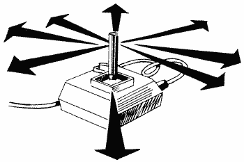
If bit two of PACTL is set, then PORTA writes to the direction control register. A direction control register, as the name implies, is used to specify the direction that information (data) is traveling on the various port pins. What are port pins? Take a close look at the controller ports and you can see them. They are numbered one through five on the top row (left to right) and six through nine on the bottom. PORTA only deals with one through four; bits zero through three represent pins one through four on jack one, while bits four through seven represent pins one through four on jack two. When bit two of PACTL is set, a bit set to one in PORTA means that the corresponding pin will be used for output. Similarly, a bit set to zero means that pin will be used for input.
You may be wondering what the other port pins are used for. Pin five is used for the right paddle value (POT1/3/5/7), pin six for the joystick button (TRIG0/1/2/3), pin seven supplies five volts to the paddles (this pin isn't connected in the joysticks), pin eight is the ground (for both joystick and paddle), and pin nine is the left paddle value POT0/2/4/6).
PORTB
54017 D301
PORTB is the same as PORTA, except it's used with controller jacks three and four rather than two and three. Also, its function is determined by PBCTL, not PACTL.

The shadow registers for PORTB and STICK2 and STICK3 (634 and 635), and PTRIG4 through PTRIG7 (640 through 643).
PACTL
54018 D302
If you have a cassette player hooked up to your computer, try putting a music cassette in it, pressing PLAY, and then entering the following statement:
POKE
54018,52
This turns on the cassette motor and lets you play music or voice through the TV speaker. To turn off the motor, use the following:
POKE
54018,60
Other uses of PACTL, which is also called the "port A controller," are as in Figure 47.
| -011--00 | (48) | disables peripheral A interrupts. |
| 0-011--01 | (49) | enables "peripheral proceed line available" interrupts (IRQ, vectored through VINTER at locations 514 and 515). |
| -011-00- | (48) | means that PORTA above will write to the direction control register. |
| -011-10- | (52) | means that PORTA will read and write to the first two controller jacks. |
| -0110-0- | (48) | turns the cassette motor on (also called peripheral motor). |
| -0111-0- | (56) | turns the cassette motor off. |
| 1011--0- | (176) | means that a "peripheral proceed line available" interrupt has occurred. You cannot write to this bit, but rather clear it by PEEKing PORTA. |
FIGURE 47. PACTL (port A controller) bit chart
A few words on the preceding values before we move on. PACTL is initialized to 60, which means that the cassette motor is turned off (bit three) and PORTA will read and write to the first two controller jacks (bit two). This piece of information should hopefully clear up a question you might have had concerning turning the cassette motor on and off. The reason the POKEs I gave you earlier are different than the bit values above is that bit two should be on in order for the joysticks and paddles to work properly. That's why we use 52 and 60 in the POKES instead of 48 and 56.
PBCTL
54019 D303
This is the port B controller and has the same functions as PACTL with the following differences:
1. Bits zero and seven deal with the
"peripheral interrupt line
available" interrupts.
2. Bit two deals with PORTB.
3. Bit three no longer controls the cassette motor but is instead used for peripheral command identification. It is not clear anywhere as to exactly what this means (although most sources also label it as the "serial bus command line"). It is initialized to one.
2. Bit two deals with PORTB.
3. Bit three no longer controls the cassette motor but is instead used for peripheral command identification. It is not clear anywhere as to exactly what this means (although most sources also label it as the "serial bus command line"). It is initialized to one.
POKEing 54019 with a 56 tells the computer to take the next POKE to 54017 as a data direction code. This is binary code with each bit corresponding to a pin on the jacks. If the corresponding bit is 1, the pin is defined as output, and if it is 0, then the pin is input. Once you have completed that section of code, you may POKE to 54017 whatever you may want to send out. If you POKE there and then PEEK the same location, you will get back the code you sent, as if it were a RAM location. This means that if you sent the low order four bits as output, and the upper four bits as input, you can send a code out, then read the input combined with the code you sent. This makes scanning the controllers simple to set up in your software. The value you read is what you sent plus 16 times the value that your device sends back.
Here is an example setting up the B port as output:
100
POKE 54019,56
110 POKE 54017,255
120 POKE 54019,60
110 POKE 54017,255
120 POKE 54019,60
The 56 tells the ATARI that the next POKE to 54017 will be a direction control code. It is in binary, so the 255 sets up all eight pins for output. The 60 is then sent out.
Noname
54020-54271 D304-D3FF
Here we are at the end of the useful PIA locations, once again faced with lots of unused locations, as in all of these.
ANTIC
We found out previously that the G/CTIA chip converts information about the screen into a form that the television set can understand. It gets most of this information from ANTIC, which in turn gets it from you.
ANTIC is like a computer within a computer. It has its own special program, called the display list, which in turn has its own special commands. These commands tell ANTIC such things as how the screen is supposed to look and where to find the data that is to appear on it. But we already know this from our discussion at SDLSTL (560,561). ANTIC also takes care of the Non-Maskable Interrupts (NMIs), fine scrolling, and various pointers, all of which will affect the way the screen will appear. Let's take a look.
DMACTL (POKE only)
54272 D400
DMACTL controls DMA (Direct Memory Access). Since there is a wonderful description of it at its shadow register, SDMCTL (559), I won't repeat myself here. There are, however, two more things to add. First of all, DMACTL must be used along with GRACTL (53277) when turning on players and missiles. Secondly, both DMACTL and GRACTL are initialized to 34.
CHACTL (POKE only)
54273 D401
CHACTL makes various changes to the way inverse characters appear and also allows you to make all characters appear upside down (what fun!). See its shadow register CHACT at location 755 for a complete description.
DLISTL, DLISTH (POKE only)
54274,54275 D402,D403
DLISTL/H specifies the address of the beginning of the display list. See its shadow register, SDLSTL, at locations 560 and 561.
HSCROL (POKE only)
54276 D404
Fine scrolling is by far one of the most impressive features the Atari has to offer. We've all been impressed by games that have smoothly scrolling playfields, and wondered, no doubt, how we could do it ourselves. HSCROL and VSCROL are the way, but unfortunately, machine language is required to get the kind of effects you've seen. Although fine scrolling can be done from BASIC, it is not nearly as smooth as machine language and is darn near impossible when you're scrolling more than one or two lines. So, although I'll cover the basics here, if you really want to learn to do great fine scrolling from machine language, check out the excellent section on scrolling in De Re Atari.
HSCROL allows you to fine scroll horizontally, one color clock at a time (a color clock is the size of a graphics mode seven pixel). It will affect every mode line that has bit four set in the corresponding display list instruction (see SDLSTL at locations 560 and 561). For example,
100
GRAPHICS 0
110 DLIST=PEEK(560)+PEEK(561)*256
120 POKE DLIST+7,18
130 LIST
140 FOR COLCLK=0 TO 15
150 POKE 54276,COLCLK
160 FOR DELAY=1 TO 50
170 NEXT DELAY
180 NEXT COLCLK
190 GOTO 140
110 DLIST=PEEK(560)+PEEK(561)*256
120 POKE DLIST+7,18
130 LIST
140 FOR COLCLK=0 TO 15
150 POKE 54276,COLCLK
160 FOR DELAY=1 TO 50
170 NEXT DELAY
180 NEXT COLCLK
190 GOTO 140
As you can see, there are a few things acting screwy here. First of all, why are the lines below the one being scrolled messed up? ANTIC expects to see 48 bytes per horizontally scrolling line instead of the regular 40. In our example, that causes the lower lines to get shifted over. The solution, and the reason that fine scrolling from BASIC is so difficult, is to give each horizontally scrolling line an LMS instruction (again, see SDLSTL). This brings us to our second problem. Why aren't the characters in our example being scrolled all the way across the screen? HSCROL can only handle values between 0 and 15. If you want to scroll more than 15 color clocks, what you have to do is set HSCROL back to 0 and change the LMS addresses of the lines you're scrolling. In graphics mode zero, for example, you would subtract four from each LMS address. Why four? Each character in graphics mode zero is 4 color clocks wide, so the equivalent of setting HSCROL to 16 would be moving the characters four to the right, which is the same as subtracting four from the LMS addresses. As I said before, this can get messy from BASIC.
Let's look at a checklist of what you need to do to have fine horizontal scrolling:
1. LMS
addresses for all the lines you are going to scroll.
2. Bit four set on all the display list instructions for the lines you are going to scroll.
3. Screen memory set up properly to account for the longer lines.
2. Bit four set on all the display list instructions for the lines you are going to scroll.
3. Screen memory set up properly to account for the longer lines.

And to do the actual scrolling:
1. Set HSCROL to 0
(15 if you're scrolling from right to left).
2. Add one to HSCROL (subtract 1). Remember that HSCROL is POKE only, so you'll have to keep track of its current value in a separate variable.
3. If HSCROL equals 16 (minus 1), set it to 0 (15) and subtract (add) 4 to each LMS address. If you're using graphics modes one or two, add or subtract 2 instead of 4, since each character in these modes is twice as wide as in graphics zero.
4. Go to step 1.
When you change the LMS addresses, you should also check to make sure that you haven't scrolled too far to the left or right.
VSCROL (POKE only)
54277 D405
VSCROL is like HSCROL, except it takes care of fine vertical scrolling. Bit five in the display list instructions is responsible for turning the scrolling on or off for each line (one equals on), and the value you POKE into VSCROL is the number of scan lines you want to scroll the lines upwards. Try the following:
100
GRAPHICS 0
110 DLIST=PEEK(560)+PEEK(561)*256
120 POKE DLIST+7,34
130 LIST
140 FOR SCNLIN=0 TO 7
150 POKE 54277,SCNLIN
160 FOR DELAY=1 TO 50
170 NEXT DELAY
180 NEXT SCNLIN
190 GOTO 140
110 DLIST=PEEK(560)+PEEK(561)*256
120 POKE DLIST+7,34
130 LIST
140 FOR SCNLIN=0 TO 7
150 POKE 54277,SCNLIN
160 FOR DELAY=1 TO 50
170 NEXT DELAY
180 NEXT SCNLIN
190 GOTO 140
There are a few things to notice here. First of all, there's no problem with the lines below the one scrolling. Vertical scrolling does not expect extra bytes per line, so there is no need to worry about that. Secondly, try BREAKing the program and then POKE 54277,0.
Where's line 120? In fine vertical scrolling, the line after the last line to be scrolled acts as a "buffer." The buffer provides data to scroll into the last scrolling line. To see this, get rid of line 190 and RUN the program again. You should always make sure that there is one nonscrolling line to act as the buffer.
Our final thing to notice here is that every now and then the sceen "jumps" a little while the program is running. This is because ANTIC does not like you changing VSCROL (or HSCROL) while it's trying to draw the screen. That means that you should take care of fine scrolling during VBLANK, which is another reason why machine language is necessary.
One nice thing about vertical scrolling is that you only need to have an LMS instruction on the first line to be scrolled. For example, try the following:
100
GRAPHICS 0
110 DLIST=PEEK(560)+PEEK(561)*256
120 POKE DLIST+3,98
130 FOR INSTR=6 TO 27
140 POKE DLIST+INSTR,34
150 NEXT INSTR
160 LIST
170 LMSLO=PEEK(DLIST+4)
180 LMSHI=PEEK(DLIST+5)
190 FOR SCNLIN=0 TO 7
200 POKE 54277,SCNLIN
210 FOR DELAY=1 TO 50
220 NEXT DELAY
230 NEXT SCNLIN
240 LMSLO=LMSLO+40
250 IF LMSLO>255 THEN LMSLO=LMSLO-256:LMSHI=LMSHI+1:POKE DLIST+5,LMSHI
260 POKE DLIST+4,LMSLO
270 GOTO 190
This program makes all the mode lines (except the last) scrollable vertically and then proceeds to scroll them. It does not check how far it's scrolled so far, so it will eventually start showing garbage on the screen. See SAVMSC at locations 88 and 89 for an explanation of why. Press SYSTEM RESET when you've had enough.
One thing you'll also see when you run this program is the main problem with fine scrolling from BASIC: You can't change the LMS address and VSCROL at exactly the same time, so the whole screen appears to "jump" down a line every so often. Although there is no way to get rid of this, you can use SDMCTL at location 559 to turn off the screen while you change the LMS. This generates a brief "flash" instead of the jump. See for yourself; add the following lines to the preceding program:
205
POKE 559,34
255 POKE 559,0
255 POKE 559,0
This is about the best you can do from BASIC.
In modes zero and one, where the characters are 8 scan lines high, VSCROL can vary from 0 to 7. In mode two, where the characters are 16 scan lines high, it can vary from 0 to 15.
Noname
54278 D406
This location is not used.
PMBASE (POKE only)
54279 D407
Back in G/CTIA, we were discussing player/missile graphics. We discovered that we could either keep supplying G/CTIA with the player/missile data ourselves, or have ANTIC do it for us. If ANTIC is doing it, them PMBASE is used to tell ANTIC where the data is stored. It is the high byte of the address, so the address itself is equal to the value you POKE into PMBASE times 256. Because of some esoteric requirements of ANTIC, PMBASE must be on a 2K boundary if you are using regular height players, and a 1K boundary if you are using double height players. How can you tell? If the value you are going to POKE into PMBASE is a multiple of four, then it's a 1K boundary. It has to be a multiple of eight to be a 2K boundary.
For a detailed explanation of how to use PMBASE and other player/missile graphics registers, see Appendix Two on - what else? - player/missile graphics.
Noname
54280 D408
Another location that isn't used.
CHBASE (POKE only)
54281 D409
Another location with a shadow register that explains everything. See CHBAS at location 756 for a description of the character set address. Also see Appendix One on designing your own character sets.
WSYNC (POKE only)
54282 D40A
Storing any value in WSYNC will cause the 6502 to stop everything until the end of the current scan line (HBLANK). This is very useful if you want to synchronize something with the screen display. For an example, and more information, see VDSLST at locations 512 and 513. Note that VDSLST is not a shadow register for WSYNC.
VCOUNT (PEEK only)
54283 D40B
VCOUNT keeps track of what scan line is currently being drawn. Actually, it increases by one every two scan lines, so multiply the value by two to get the true number.
If you have more than one DLI, VCOUNT is a good way for your DLI routine to check which one is being processed. It can also be used to simulate DLIs. For example, you might write a loop that waits for VCOUNT to reach a certain value before going on. This allows you to spend more time in a certain routine than DLIs allow, but it also wastes a lot of time waiting.
There are a total of 262 scan lines on a screen (312 in Europe), so VCOUNT can range from 0 to 130 (155 in Europe).
PENH (PEEK only)
54284 D40C
This tells you the horizontal position of the light pen. See its shadow register, LPENH, at location 564 for more information.
PENV (PEEK only)
54285 D40D
Same as the preceding, except it's the vertical position and you should see LPENV at location 565.
NMIEN (POKE only)
54286 D40E
The last two bits of NMIEN are used to enable or disable the NMIs. They are used as shown in Figure 48.
| --1----- | (32) | enables the SYSTEM RESET interrupt. |
| -1------ | (64) | enables the vertical blank interrupt. |
| 1------- | (128) | enables the display list interrupt. |
FIGURE 48. NMIEN bit chart
The OS initializes NMIEN to 64, thereby enabling vertical blank interrupts. It also sets NMIEN to 64 during the SETVBV routine mentioned at VVBLKD (548,549). So what? If you are writing a program where you will be using your own VBLANK routine and display list interrupts, make sure that you enable the display list interrupts after you use SETVBV. There have been a couple of times when I couldn't figure out why my DLIs weren't working, only to discover that I had enabled them before I set up my VBLANK routine.
A few of you out there may be thinking "What about SYSTEM RESET, isn't that an NMI as well?" Yes it is, but the computer does not allow you to disable it. Pressing SYSTEM RESET will always cause a warm start to occur. You can, however, store an address in DOSINI (12,13), since the OS jumps through DOSINI after it is done with the warmstart. Most machine language programmers have DOSINI point to their program's initialization routine. That way, the program will start over again if someone presses SYSTEM RESET (normally the OS would go to BASIC or reboot the system).
NMIRES (POKE) and NMIST (PEEK)
54287 D40F
(POKE) POKEing any value here clears NMIST.
(PEEK) The last three bits of NMIST are used to identify what kind of interrupt has occurred (Figure 49).
| --1----- | (32) | means that the SYSTEM RESET key has been pressed. |
| -1------ | (64) | means that a vertical blank interrupt has occurred. |
| 1-------
|
(128) | means
that a display list interrupt has occurred. |
FIGURE 49. NMIST bit chart
Unfortunately, since the OS has already take care of NMIST and WIRES by the time you can get to them, they don't really do you much good (you don't have to reset NMIST during your DLI routine).
Noname
54288-54783 D410-D5FF
These locations, the rest of ANTIC, are currently unused.
Noname
54784-55295 D600-D7FF
So are these.
Return to Table of Contents | Previous Chapter | Next Chapter

