4
Getting a Player
on the Screen
Now that you have designed a player and have allocated space for PMG memory, let's see what that player looks like.
- When you finish this chapter you will be able to:
- Write the code needed to get a player on the screen.
- Put the player anywhere you want by specifying horizontal and vertical coordinates.
- Make the player any desired color.
- Use double-line resolution.
To start with, let's go over the main programming tasks required to get a player on the screen.
MAIN PROGRAMMING TASKS
- Define filler strings so that the PM strings area can start on a 1K boundary.
- Allocate space for the PM memory area.
- Set the PM memory area to zeros.
- Dimension a separate string for holding our player image data.
- Put our player data into that string.
- Specify the color of our player.
- Specify the location of PM memory.
- Specify double-line resolution.
- Turn on PMG.
- Specify the desired horizontal location of the player.
- Put player image into the desired vertical location.
You have already learned to write the code for steps 1 and 2. so let's go on to step 3.
Setting the PM Memory Area to Zeros
When you run a program, the data in the string area is not automatically cleared out. That's why we need to explicitly set the PM memory area to zeros. Let's start with BUFFER$. Here's a quick way to set it to zeros:
11020 BUFFER$=CHR$(0)
11030 BUFFER$(384)=CHR$(0)
11040 BUFFER$(2)=BUFFER$
This code may seem somewhat confusing, but rest assured--it works. Line 11020 sets the first byte of BUFFER$ to zero. Line 11030 sets the 384th byte to zero. Line 11040 says "start with the second byte of BUFFER$ and set all the remaining bytes of BUFFER$ to the first byte of BUFFER$." (I know, it's a mouthful.)
As an aside, if you wanted to set all of BUFFER$ to some other value besides zeros, all you need to do is to change line 11020. For example to set BUFFER$ so that it has nothing but "X's," change line 11020 to read:
11020 BUFFER$="X"
If you'd like to take a break from reading, you may want to enter the above lines and experiment with changing line 11020 to see what affect it has on BUFFER$. If so. I suggest you start by entering these lines:
11010 DIM BUFFER$(384)
11020 BUFFER$="X"
11030 BUFFER$(384)=CHR$(0)
11040 BUFFER$(2)=BUFFER$
11050 ? BUFFER$
Note that in line 11020 we set the first byte of BUFFERS to "X." In line 11050 we print BUFFER$ just to see what it contains. (The question mark is short for "PRINT.")
After entering the lines, type "RUN." Since all of BUFFER$ has been set to "X," you will see this:
Now, change line 11020 so that it reads:
11020 BUFFER$=CHR$(0)
Run the program again. This time you will see a screen full of hearts. That's because the Atari code for a heart character is a zero.
- Think for a moment. Does the memory location of BUFFER$ contain hearts or zeros?
a. Hearts
b. Zeros
|
||||||
To see the zeros in BUFFER$, try running this program:
11060 FOR I=1 to 384
11070 ? ASC(BUFFER$(I))
11080 NEXT I
Note: In line 11070 I am using "ASC" to return the actual number stored in each byte of BUFFER$ rather than displaying a character.
Now that we have set BUFFER$ to zeros, we can use it to set the rest of PM memory to zeros. For example, we can set the missile area to zeros like this:
MISSILES$=BUFFER$
- You try it. Assume that BUFFER$ has already been set to zeros. Then, write the statements needed to set the entire PM memory area to zeros. (Remember, besides BUFFER$, our PM memory area contains these strings: MISSILES$, PLAYER0$, PLAYER1$, PLAYER2$, PLAYER3$.)
|
||||||
Player Image String
Besides dimensioning the PM memory area and setting it to zeros, we need to dimension a string to hold our player image data. We'll call it "IMAGE1$," meaning "image one for player one." As you will see later, we will want to have more than one image for each of our players so that we can do things like make their legs move.
Dimensioning the string is easy:
DIM IMAGE1$
Putting the proper data into a string is a bit harder. First, you need to know how to refer to specific bytes of a string. If you already know how to do that, you may wish to skip ahead to "Putting Data into IMAGE1$."
Referencing Specific Bytes
In Atari BASIC, you can refer to specific sections of a string variable by numbers in parentheses after the name of the string. The first number gives the starting byte of the section of the string you want to refer to. The second number gives the ending byte. For example, to refer to the first three bytes of a string called STORAGE$, we would write:
- How would you refer to bytes 5 through 9 of STORAGE$?
|
||||||
If you want to refer to a single byte, just list the number of that byte twice. For example, to refer to byte 5 of STORAGE$, you would write:
STORAGE$(5,5)
- How would you refer to byte 15 of STORAGE$?
|
||||||
Putting Data Into IMAGE1$
To get out player image data into the string we use a "FOR-NEXT" loop. Our first statement in this loop is:
FOR I=1 to 15
This sets up the loop so that I is set to 1 the first time through the loop. The next time through the loop. I will be set to 2 and so on until I is 15.
- Can you guess why we need to make 15 passes through the loop?
|
||||||
Here is the complete loop for putting all 15 numbers into IMAGE1$:
FOR I=1 TO 15:READ A:IMAGE1$(I,I)=CHR$(A):NEXT I
Let's look at each statement separately. We've already discussed "FOR I=1 TO 15." The next statement is "READ A."
READ A This simply gets a number contained in a data statement and puts it in variable A.
IMAGE1$(I,I)=CHR$(A) This statement puts the number into successive bytes of IMAGE1$. Note the (I,I). The first time through the loop the variable I will be set to 1. So the statement will be equivalent to:
IMAGE1$(1,1)=CHR$(A)
This means set the first byte of IMAGE1$ to the contents of variable A. The second time through the loop, I will be set to 2. So the statement will be equivalent to:
IMAGE1$(2,2)=CHR$(A)
- What does this mean?
|
||||||
Now let's talk about CHR$(A). We need this because the variable A is numeric. You can't put numeric data into a string directly. It has to be converted to string data (also referred to as character data). That's what CHR$ does. It takes whatever number is in parentheses and gets the corresponding character, which can then be stored in the string.
- What do you think would happen if we simply wrote:
IMAGE1$=A
|
||||||
Now that we have set the PM memory area to zeros, our next step is to specify what color we would like our player to be.
Specifying Player Color
You can easily control the color of a player by putting a number into a memory location. Here are the locations for each of the players:
|
Player 0 1 2 3 |
Location 704 705 706 707 |
(For your convenience these locations are also summarized in Appendix A.)
If you use graphics modes 3, 5, or 7, then you can use the following numbers as a guide for designating your player's color:
|
Color Gray Gold Orange Red Pink Violet Purple Blue Blue Light Blue Turquoise Blue-Green Green Yellow-Green Orange-Green Light Orange |
Number 0 16 32 48 64 80 96 112 128 144 160 176 192 208 224 240 |
These are starting numbers. To any given number you can add an even number from 0 to 14 to change the lightness of the color. For example, for a light green color you might add 14 to 192 and use 206 as the color number. For a darker green you might add, say, 4 to 192 and use 196.
- Would 48 give you a bright red or dark red color?
|
||||||
- What number would you use for a light red?
|
||||||
You might also use 56, 58, or 60 for a light red, depending on how light a shade you want. Notice that when you go beyond 62, you start moving into pink.
Poking the Color Number
You can use the Poke command to specify the player's color. To specify a dark gold color for player 0, you might write:
POKE 704,16
- Write a command to set player 2's color to dark violet.
|
||||||
Specifying Start of PM Memory
The Atari microprocessor called ANTIC automatically takes care of displaying PM images on the screen. But before ANTIC can do that we have to tell it where PM memory starts. To do that we simply POKE the proper address into location 54279. Since our PM memory area is string memory, we can use the ADR function. The ADR function gives the address of the string that follows it in parentheses. For example:
ADDRES$=ADR(STORAGE$)
After this statement is executed, the variable ADDRES$ will contain the starting address of the string area called STORAGE$.
- Recall the structure of the PM memory area. What is the first string in the PM memory area?
|
||||||
- How would you refer to the address in memory where BUFFER$ starts?
|
||||||
- From what you've learned, see if you can write a statement to inform ANTIC of the location of the PM memory area.
|
||||||
PMBASE
Location 54279 is known as the Player-Missile Base Register (PMBASE). If you initialize a variable called PMBASE to 54279 at the beginning of the program like this
PMBASE=54279
then we can tell ANTIC where PM memory starts by writing a statement like this:
POKE PMBASE,ADR(BUFFER$)
Did you notice how I use the word "register" above to refer to a memory location? (Player-Missile Base Register=location 54279.) Remember, in data processing, a register is nothing more than a memory location dedicated to a specific purpose. Usually we put data into a register to control the computer's operation.
Specifying Resolution
Another important register is the one used to specify resolution. We touched on resolution earlier, but now let's consider it in more detail. With PMG you have your choice of either double- or single-line resolution. Single-line resolution means that when ANTIC sees a "1" in PM memory it will light up a single pixel.
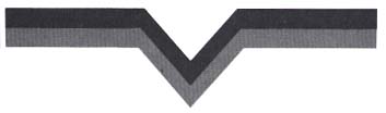
In double-line resolution, when ANTIC sees a "1" in PM memory it lights up two pixels. Both pixels will be right underneath each other on two separate lines (hence the name double-line resolution). Perhaps an illustration will help clarify this. Suppose you have this binary data in PM memory:
00011100
00011100
00001000
00011100
00111010
01011001
00011000
00111100
00100100
00100100
01100110
With single-line resolution, your player will look like this:
With double-line resolution, you will get a player that looks like this:
- Which kind of resolution gives you a more "blocky" looking character? Which one looks more "detailed"?
|
||||||
- So far we have been using double-line resolution. How many bytes per player does double-line resolution require? (Hint: look back at how we dimensioned each player.)
|
||||||
If we were to use single-line resolution we would need twice as many bytes for each player because each bit in memory only lights up one pixel.
- How many bytes would each player need in single resolution?
|
||||||
Keep in mind that if we dimension our players for 128 bytes, then we must use double-line resolution. We can't change to single-line resolution, unless we change the way we dimension PM memory. Also, the filler strings (remember them?) must be dimensioned differently because single-line resolution must start on a 2K boundary. (More on single-line resolution later.)
- We can ask for double-line resolution by poking location 559 with 46. How would you code that?
|
||||||
Location 559 is called the direct memory access control register (DMACTL). It is used for more than just specifying the type of resolution. We'll talk more about DMACTL later. For now just note that you need to poke it with 46 to ask for double-line resolution. As we did before, you could use DMACTL as a variable in place of "559." At the beginning of the program you could write:
DMACTL=559
- What is the other statement needed to ask for double-line resolution?
|
||||||
Turning on PMG
Another important register is memory location 53277. called the graphics control register (GRACTL). You use GRACTL to "turn on" the PMG system. You have different options here. You can turn on just players, just missiles, or players and missiles. Here's how you do it:
| If you want: | Then: |
|---|---|
|
Missiles only Players only Players and missiles |
POKE 53277,1 POKE 53277,2 POKE 53277,3 |
- Suppose you want to use players and missiles. How do you specify this with the GRACTL register?
|
||||||
Using Register Abbreviations
If you want, you can also initialize the variable GRACTL to 53277 at the beginning of your program like this:
GRACTL=53277
Then, to turn on PMG with both players and missiles, you could write:
POKE GRACTL,3
- Can you think of a disadvantage in doing it this way? An advantage?
|
||||||
Well, we're almost there. Once you have taken care of these steps you have completed the task of setting up PMG. Often you will need to carry out these steps only once, so it's a good idea to put the code needed to do this into a subroutine.
Assigning Line Numbers As a rule of thumb, I suggest you assign high numbers to subroutines that will be performed just once or when speed is not critical. That's because when Atari BASIC executes a subroutine, it has to search for it sequentially, starting with the lower line numbers.
- Because the PMG setup routine will usually be done just once at the beginning of the program, which of these line numbers do you think would be most appropriate for it?
a. 100
b. 500
c. 11000
|
||||||
Once the setup routine is complete, all you need to do is say where you want the player to appear on the screen horizontally and vertically. Let's take the horizontal specification first, since it's the easiest. We use a set of registers for that--the horizontal position registers for players (HPOSP0 to HPOSP3).
HPOSP0
HPOSP0 is the horizontal position register for player 0. It is memory location 53248.
Here are the values you poke for various horizontal screen locations:
Check your understanding:
- Write a statement to put player 0 at the:
1. Left edge of the screen.
2. Right edge of the screen.
3. Center of the screen.
|
||||||
- Where do you think the horizontal position register is for:
1. player 1
2. player 2
3. player 3
|
||||||
Often it's handy to use a variable to specify the value to be poked into the horizontal position register. For example, you might use H1 to designate the horizontal coordinate for player 1. Then you would write:
POKE 53248,H1 or POKE HPOS0,H1
More on why this is useful later. Let's now look at how you set the vertical position of a player.
Vertical Position
Atari BASIC doesn't have a vertical position register. So specifying vertical position can be a problem. But because we use string memory for PMG, it's easy to specify vertical position. First, set a variable like, say, "vert" to the desired value:
VERT=30
Then use a string command to set the player string to the data contained in the player image string, like so:
PLAYER0$(VERT)=IMAGE1$
Remember our discussion of how string commands work? The value in parentheses after the string specifies the starting byte. If VERT equals, say, 30, then the data in IMAGE1$ will be placed in PLAYER0$ starting with the 30th byte. This has the effect of displaying our player at vertical position 30.
- If we wanted to position our player at vertical position 80, we would poke the image data into the 80th byte of the player string. Altogether our player string has 128 bytes, so how many vertical positions do we have available?
|
||||||
- Write the two statements needed to put player 1 at vertical position 80. Use the data contained in IMAGE1$. Use the variable VERT to specify the 80th byte of PLAYER1$.
|
||||||
TRYING IT OUT
Well that's it! Now let's put this all together and get that player on the screen. A complete program appears on the next page. Look it over briefly. Then read the comments that follow it. For your convenience, I have listed the program so that each line has no more than 38 characters. This way the printed listing will match up with your screen listing.
Caution: Be careful in typing X0 and Y0 at lines 13000 and 13010 (and elsewhere in the program). "X0" is "X zero," not "XO." Notice the difference? The zero is more oval shaped than the letter "0."
The zero represents player number 0. "X0" contains the horizontal position for player 0. "Y0" contains the vertical position for player 0. Of course, you can adopt any variable naming scheme that you want. Just be consistent. Don't type "Y0" one time and "YO" the next.
Comments on Program
This program will let you look at all the different colors that a player can be. We have already gone over the code in detail so I will just comment briefly on a few points of interest.
ONSCREEN.BAS
Download (Saved BASIC)
Download / View (Listed BASIC)
Line 1: GOSUB 2000 As you can see I start the program by "calling" a subroutine at line 2000. The purpose of this subroutine is to take care of what are sometimes called "housekeeping routines." These are routines that you usually only need to do once at the beginning of the program. By using high line numbers for these setup routines, I leave space at the beginning of the program for the main routine. This is preferable because routines requiring transfer of control (GOTOs or GOSUBs) execute faster if they are placed at the beginning. This will become more important later when our main routine becomes more complex.
Notice that the subroutine at line 2000 calls these additional setup routines:
10000 Miscellaneous Initialization
11000 PMG Setup
12000 Drawing of Playfield
13000 Beginning Player Color and Screen Position
The "playfield" referred to here is simply the screen image that the player moves around on. In this case, I have used a few PLOT and DRAWTO statements to create a simple playfield. Notice that I set the graphics mode before doing the PMG setup. This is important because once the PMG setup is done, the graphics mode should not be changed. (Actually, you could change the graphics mode after setting up PMG, but then you need to call the PMG setup routine all over again.)
I won't go into the details of how to create playfields. For details on playfield creation, you may wish to refer to Designs from Your Mind with Atari by Tom Rowle (Reston, 1983).
Line 2: GOTO 200 Obviously this line transfers control to line 200. But why? Simply because we want to jump over line 3, which is really not part of the program.
Line 3: SAVE "D:ONSCREEN.SAV":STOP I use this line to save the program to disk after I've made changes to it. It's really quite handy. After I've finished editing the program, I just type G.3 and the program starts saving itself! (Atari understands that "G." is an abbreviation for "GOTO.") Notice the command "STOP" at the end of line 3. This keeps the program from continuing to execute after it saves itself.
Line 200 to 240 Here is where the main "activity" in the program occurs. Notice that I have created a loop in which successive even numbers are poked into location 704, which is the color control register for player 0.
AN ASSIGNMENT
I suggest you type the program into memory. Then save it by typing G.3. Next, try running it. If it doesn't work, proofread your work carefully. Watch out for typos! They are especially destructive when you are working with PMG. That's why it's important to save the program before running it.
Once the program is working, you may wish to try modifying it slightly. That's the best way to learn. For example, you might try changing the values following the SETCOLOR command at line 13000. If you do, notice how this affects the color of the playfield and the player. Or, try changing the horizontal and vertical position of the player. You can do that by changing the values assigned to X0 and Y0 in the subroutine starting at line 13000. Happy hacking!
Return to Table of Contents | Previous Chapter | Next Chapter