Chapter Seven
Looping Around and Branching Out
Now we’re going to start having some fun with Atari assembly language. In this chapter, you’ll learn how to print messages on the screen, how to encode and decode ATASCII (Atari ASCII) characters, and how to perform other neat tricks in assembly language. We’re going to accomplish these feats with some advanced assembly language programming techniques that we haven’t tried out so far, along with some new variations on techniques covered in earlier chapters. These are some of the programming techniques we’re going to cover in this chapter.
- Using the assembly language .BYTE directive.
- Incrementing and decrementing the X and Y registers.
- Using comparison and branching instructions together.
- Advanced looping and branching.
- Writing relocatable assembly language instructions.
Before we get started, though, I’m going to pull a very sneaky trick. I’m going to ask you to type up and store on a disk a program that you haven’t been introduced to. You probably won’t understand it unless you’ve had previous experience in assembly language programming. I’m asking you to type this program because it contains a couple of subroutines that are needed to run two other programs, programs that will be introduced and explained in this chapter. The program you may not understand is one that will be explained in Chapter 12, I/O and You.
Two Good Reasons
There are two rather sophisticated but extremely useful subroutines in this program. One is a routine that will open your screen as an output device and put your Atari into its screen edit disk, you’ll already have that job done the next time you encounter them, in I/O and You. So I hope you’ll look ahead to greener pastures in the last chapter of this book, and not be too angry at me for asking you to type this program now.
PROGRAM FOR PRINTING ON THE SCREEN
10 ;
20  .TITLE "PRNTSC ROUTINE"
30  .PAGE "ROUTINE FOR PRINTING ON THE SCREEN"
40 ;
50  *=$5000
60 ;
70 BUFLEN=23
80 ;
0100 EOL=$9B
0105 ;
0110 OPEN=$03
0120 OWRIT=$0B
0130 PUTCHR=$0B
0135 ;
0140 IOCB2=$20
0170 ICCOM=$342
0180 ICBAL=$344
0190 ICBAH=$345
0200 ICBLL=$348
0210 ICBLH=$349
0220 ICAX1=$34A
0230 ICAX2=$34B
0235 ;
0240 CIOV=$E456
0250 ;
0260 SCRNAM .BYTE "E:",EOL
0270 ;
0280 OSCR LDX #IOCB2;OPEN SCREEN ROUTINE
0300  LDA #OPEN
0310  STA ICCOM,X
0320 ;
0330  LDA #SCRNAM&255
0340  STA ICBAL,X
0350  LDA #SCRNAM/256
0360  STA ICBAH,X
0370 ;
0380  LDA #OWRIT
0390  STA ICAX1,X
0400  LDA #0
0410  STA ICAX2,X
0420  JSR CIOV
0430 ;
0440  LDA #PUTCHR
0450  STA ICCOM,X
0460 ;
0470  LDA #TXTBUF&255
0480  STA ICBAL,X
0490  LDA #TXTBUF/256
0500  STA ICBAH,X
0510  RTS
0520 ;
0530 PRNT
0540  LDX #IOCB2
0550  LDA #BUFLEN&255
0560  STA ICBLL,X
0570  LDA #BUFLEN/256
0580  STA ICBLH,X
0590  JSR CIOV
0600  RTS
0610 ;
0620 TXTBUF=*
0630 ;
0640  *=*+BUFLEN
0650 ;
0660  .END
Download / View (Assembly source code)
Now Save It!
When you have this program typed, you can assemble its object code and save it on a disk under the filename PRNTSC.OBJ. Then there’s one other program I’d like for you to type and assemble. It’s the one we’ll be working with the rest of this chapter.
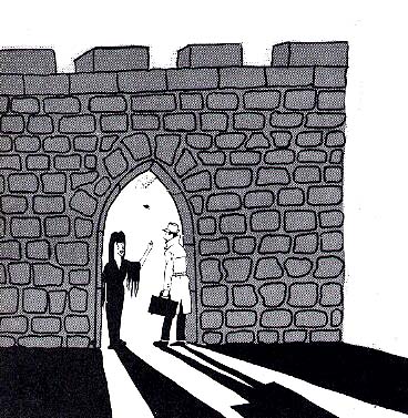
THE VISITOR
10 ;
20 ; THE VISITOR
30 ;
35 TXTBUF=$5041
40 OPNSCR=$5003
50 PRNTLN=$5031
70 ;
80  *=$600
90 ;
0100 TEXT .BYTE $54,$41,$4B,$45,$20,$4D,$45,$20
0110  .BYTE $54,$4F,$20,$59,$4F,$55,$52,$20
0120  .BYTE $4C,$45,$41,$44,$45,$52,$21
0130 ;
0140 VIZTOR
0150 ;
0160  LDX #0
0170 LOOP LDA TEXT,X
0180  STA TXTBUF,X
0190  INX
0200  CPX #23
0210  BNE LOOP
0220  JSR OPNSCR
0230  JSR PRNTLN
0240 INFIN JMP INFIN
Download / View (Assembly source code)
This program is called (for reasons you’ll soon discover) The Visitor. It’s a program that’s designed to print a cryptic message on our video screen.
Running 'The Visitor'
When you've finished typing The Visitor, you can run it immediately. Just assemble it, and then load the object code of the PRNTSC program into your computer. Then you can run The Visitor either by putting your computer into its DEBUG mode and typing G617, or by getting into DOS mode and running The Visitor with a DOS command. When you've finished typing out The Visitor program, it wouldn't be a bad idea to save it, too, on a disk. The suggested file name for the program is VISTOR.SRC. After you've run and saved the program, you'll know exactly what it does. So now we can explain how it does what it has done. We'll start with an explanation of the assembly language .BYTE directive, which you'll see in lines 100 to 120.
The .BYTE Directive
The .BYTE directive is sometimes called a pseudo operation code, or pseudo op, because it appears in the op code column of assembly language source code listing but is not actually a part of the 6502 assembly language instruction set. Instead, it's a specialized directive designed that can be used with some assemblers, but not with others. For example, .BYTE works with both the MAC/65 assembler and the Atari assembler Editor, but does not work with the Atari Macro Assembler and Text Editor. When you write a program with the Atari Macro Assembler and Text Editor, you have to use the letters DB in place of the .BYTE directive. Other pseudo ops also differ from assembler to assembler. There are no generally accepted standards for writing pseudo op directives, so pseudo op codes designed for one assembler often won't work with another.
What the .BYTE Directive Does
When the .Byte directive is used in a program created with the MAC/65 assembler or the Atari Assembler Editor, the bytes that follow the directive are assembled into consecutive locations in RAM. In the program called The Visitor, the bytes that follow the label TEXT are ATASCII (Atari ASCII) codes for a series of text characters.
Looping the Loop
As we explained in Chapter 6, the X and Y registers in the 6502 chip can be progressively incremented and decremented during loops in a program. In the Visitor program, the X register is incremented from 0 to 23 during a loop in which characters in a text string are read. The characters that to be read are written as ATASCII codes in lines 100 through 120 of the program. In line 160, the statement LDX #0 is used to load the X register with a zero. Then, in line 170, the loop begins.
Incrementing the X Register
The first statement in the loop is LDA TEXT, X. Each time the loop cycles, this statement will use indexed addressing to load the accumulator with an ATASCII code for a text character. Then, in line 180, the indexed addressing mode will be used again, this time to store the character in a text buffer. When the loop ends, all of the characters in the text buffer will be printed on the screen. The first time the program hits line 170, there will be a 0 in the X register (since a 0 has just been loaded into the X register in the previous line). So the first time the program encounters the statement LDA TEXT, X, it loads the accumulator with the hexadecimal number $54 - what programmers sometimes call the "0th" byte after the label TEXT. (There's no need for a "#" symbol in front of the number $54, incidentally, since numbers that follow the .BYTE directive are always interpreted by the MAC/65 assembler and the Atari Assembler Editor as literal numbers.)
Incrementing and Decrementing the X and Y Registers
Now let's move on to line 190. The mnemonic you see there - INX - means "increment the X register." Since the X register currently holds a 0, this instruction will now increment that 0 to a 1. Next, in line 200, we see the instruction CPX #23. That means "compare the value in the X register to the literal number 23." The reason we want this comparison to be performed is so we can determine whether 23 characters have been printed on the screen yet. There are 23 characters in the text string that we're printing, and when we've printed all of them, we'll want to print a carriage return and end our program.
Comparing Values in Assembly Language
There are three comparison instructions in 6502 assembly language: CMP, CPX, and CPY. CMP means "compare to a value in the accumulator." When the instruction CMP is used, followed by an operand, the value expressed by the operand is subtracted from the value expressed by the operand is subtracted from the value in the accumulator. This subtraction operation is not performed to determine the exact difference between these two values, but merely to test whether or not they are equal, and if they are not equal, to determine which one is larger than the other. If the value in the accumulator is equal to the tested value, the zero (Z) flag of the processor status (P) register will be set to 1. If the value in the accumulator is not equal to the tested value, the Z flag will be left in a cleared state.
If the value in the accumulator is less than the tested value, then the carry (C) flag of the P register will be left in a clear state. And if the value in the accumulator is greater than or equal to the tested value, then the Z flag will be set to 1 and the carry flag will also be set, CPX and CPY work exactly like CMP, except that they are used to compare values with the contents of the X and Y registers. They have the same effects that CMP has on the status flags of the P register.
Using Comparisons and Branching Instructions Together
The three comparison instructions in Atari assembly language are usually used in conjunction with eight other assembly language instructions - the eight conditional branching instructions that we mentioned in Chapter 6. The sample program that we have called The Visitor contains a conditional branching instruction in line 210. That instruction is BNE LOOP, which means "branch to the statement labeled LOOP if the zero flag (of the processor status register) is set." This instruction uses what can be a confusing convention of the 6502 chip. In the 6502's processor status register, the zero flag is set (equals 1) if the result of an operation that has just been performed is 0. And the zero flag is cleared (equals 0) if the result of an operation that has just been performed is not zero.
It Really Doesn't Matter
This is all quite academic, however, as far as the result of the statement BNE LOOP is concerned. When your computer encounters line 210, it will keep branching back to line 170 (the line labeled LOOP) as long as the value of the X register has not yet been decremented to zero. Once the value of the X register has been decremented to zero, the statement BNE LOOP in line 210 will be ignored, and the program will move on to line 220, the next line. In line 220, the program will jump to the subroutine OPNSCR - which currently resides in RAM beginning at memory address $5041, provided the object code for both PRNTSC and VISITOR have been loaded into your computer and are ready to run.
Conditional Branching Instructions
As we pointed out in the previous chapter, there are eight conditional branching instructions in 6502 assembly language. They all begin with the letter B, and they're also called relative addressing, or branching instructions. These eight instructions, and their meanings, are:
BCC - Branch if the carry (C) flag of the processor status (P) register is clear.
    (If the carry flag is set, the operation will have no effect.)

BCS - Branch if the carry (C) flag is set.
    (If the carry flag is clear, the operation will have no effect.)

BEQ - Branch if the result of an operation is zero (if the zero (Z) flag is set).

BMI - Branch on minus (if an operation results in a set negative (N) flag.

BNE - Branch if not equal to zero (if the zero (Z) flag isn't set).

BPL - Branch on plus (if an operation results in a cleared negative (N) flag).

BVC - Branch if the overflow (V) flag is clear.

BVS - Branch if the overflow (V) flag is set.
How Conditional Branching Instructions are Used
To use a conditional branching instruction in 6502 assembly language, the usual method is to load the X or Y register with a zero or some other value, and then to load the A register (or a memory register) with a value to be used for a comparison. After that is done, a conditional branching instruction is used to tell the computer what P register flags to test, and what to do if these tests succeed or fail. This all sound very complicated - and it is. But once you understand the general concept of conditional branching, you can use a simple table for writing conditional branching instructions. Here's one such table.
TO TEST FOR     DO THIS     AND THEN THIS

A = VALUE       CMP #VALUE  BEQ
A <> VALUE      CMP #VALUE  BNE
A >= VALUE      CMP #VALUE  BCS
A > VALUE       CMP #VALUE  BEQ and then BCS
A < VALUE       CMP #VALUE  BCC
A = [ADDR]      CMP $ADDR   BEQ
A <> [ADDR]     CMP $ADDR   BNE
A >= [ADDR]     CMP $ADDR   BCS
A > [ADDR]      CMP $ADDR   BEQ and then BCS
A < [ADDR]      CMP $ADDR   BCC

X = VALUE       CPX #VALUE  BEQ
X <> VALUE      CPX #VALUE  BNE
X >= VALUE      CPX #VALUE  BCS
X > VALUE       CPX #VALUE  BEQ and then BCS
X < VALUE       CPX #VALUE  BCC
X = [ADDR]      CPX $ADDR   BEQ
X <> [ADDR]     CPX $ADDR   BNE
X >= [ADDR]     CPX $ADDR   BCS
X > [ADDR]      CPX $ADDR   BEQ and then BCS
X < [ADDR]      CPX $ADDR   BCC

Y = VALUE       CPY #VALUE  BEQ
Y <> VALUE      CPY #VALUE  BNE
Y >= VALUE      CPY #VALUE  BCS
Y > VALUE       CPY #VALUE  BEQ and then BCS
Y < VALUE       CPY #VALUE  BCC
Y = [ADDR]      CPY $ADDR   BEQ
Y <> [ADDR]     CPY $ADDR   BNE
Y >= [ADDR]     CPY $ADDR   BCS
Y > [ADDR]      CPY $ADDR   BEQ and then BCS
Y < [ADDR]      CPY $ADDR   BCC
Assembly Language Loops
In 6502 assembly language, comparison instructions and conditional branch instructions are usually used together. In the sample program called The Visitor, the comparison instruction CPX and the branch instruction BNE are used together in a loop controlled by the incrementation of a value in the X register. Each time the loop in the program goes through a cycle, the value in the X register is progressively incremented or decremented. And each time the program comes to line 200, the value in the X register is compared to the literal number 23. When that number is reached, the loop ends. The program will therefore keep looping back to line 170 until 23 characters have been printed on the screen. Then, in lines 220 and 230, it will open your computer's screen - clearing it in the process - and will print the string that has been transferred into the text buffer on the screen. Finally, at line 240, the program will go into what's known as an infinite loop - cycling back to the same JMP instruction over and over again, and doing nothing else until you push the break key or in some other way halt the program.
Why Use A Buffer?
Before we move on to our next topic - improving The Visitor program - it might be worthwhile to answer a question that may or may not have occurred to you. The question is: Why use a text buffer? Why not just print the text in lines 100 to 120 directly onto the screen, without moving it first into a buffer and then out again?
Here is the answer to that question: Text can be loaded into a buffer in many ways: from a keyboard or from a telephone modem, for example, as well as being loaded in as data directly from a program. And, once a string is in a buffer, it can be removed from the buffer in just as many different ways. Another advantage of a text buffer is that you can load it into RM, note its address, and use it from then on whenever you like. A buffer can therefore serve as a central repository for text strings, which will then be accessible with great ease and in many different ways.
Improving the Visitor Program
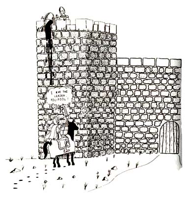
Now we're ready to make some improvements in the program called The Visitor. Not that the program doesn't work; it does, but it has certain limitations. And some of those limitations could be removed quite easily - as they have been in this new program, which I've called Response.
Response is quite similar to The Visitor - but, as you will soon see, significantly better in several ways:
RESPONSE
10 ;
20 ; RESPONSE
30 ;
40 TXTBUF=$5041
50 OPNSCR=$5031
60 PRNTLN=$5031
70 ;
80 EOL=$9b
90 ;
100  *=$650
110 ;
120 TEXT .BYTE "I AM the leader, you fool!",EOL
130 ;
140 RSPONS
150 ;
160  LDX #0
170 LOOP
180  LDA TEXT, X
190  STA TXTBUF, X
200  CMP #$9B
210  BEQ FINI
220  INX
230  JMP LOOP
240 FINI
250  JSR OPNSCR
260  JSR PRNTLN
270 INFIN
280  JMP INFIN
Download / View (Assembly source code)
If you want to run the Response program - and I hope you do - you can type it into your computer's memory right now. Since it calls the same subroutines that its predecessor did, you can assemble it and run it as soon as it's typed, provided you still have the program called PRNTSC loaded into RAM.
To run the Response program, you can either call your debugger program and use a G command, or go into DOS mode and use a DOS command. Whichever mode you decide to use, you should be able to run the program using a run address of $066B, provided that you've typed it and assembled it in accordance with the suggestions that I've provided. Even if you've followed the instructions, though, you'll still encounter one small problem. Only the first 23 character of the string "I AM the leader, you fool!" will print out on your computer screen. That's because the text buffer that we created in the program PRNTSC is only 23 characters long.
That flaw is easy to remedy. But before we fix it, it might me a good idea to save Response on a disk, in both its source code and object code versions. The program's suggested file names are RESPONSE.SRC and RESPONSE.OBJ.
Fixing The PRNTSC Program
Now we're ready to lengthen the text buffer used in the PRNTSC program, so that it will print its complete message on your computer screen. To lengthen the print buffer, just put your assembler into its editor mode and load the program's source code into your computer's memory. Then you can change line 70 from BUFLEN=23 to BUFLEN=40. When you've made this change, you can save the amended source code under the file namePRNTSC.SR2, assemble the program, and save the object code PRNTSC.SR2, assemble the program, and save the object code under the name PRNTSC.OB2 (to distinguish it from PRNTSC.SRC and PRNTSC.OBJ, your original PRNTSC programs).
When you've saved your PRNTSC.SR2 and PRNTSC.OB2 programs, you can reload the Response program and run it with PRNTSC.OB2 instead of PRNTSC.OBJ. This time you should see the full string that the Response program calls for on your video screen - but, unfortunately, you'll now notice something else wrong. After the line, "I AM the leader, you fool!" you'll see a line of little hearts. How did they get there? I'll answer that question in just a moment. But first, let's take a look at some of the differences between the program called The Visitor and the one called Response.
A Better Routine
From a technical point of view, the Response program is better than The Visitor - for several reasons. The most obvious difference between the two programs is the way they handle text strings. In the program called The Visitor, we used a text string made up of actual characters. That made the program much easier to write - and it makes it much easier to read, too.
Another important difference between our newest program and its predecessor is the way the loop is written. In the program called The Visitor, the loop counted the number of characters that had been printed on the screen, and ended when the count hit 23. Now that's a perfectly good system - for printing text strings that are 23 characters long. Unfortunately, it isn't so great for printing strings of other lengths. So it isn't a very versatile routine for printing characters on a screen.
Testing for a Carriage Return
The Response program is much more versatile than The Visitor because it can print strings of almost any length on a screen. That's because it doesn't keep track of the number of characters it has printed by maintaining a running count of how many letters have been printed on the screen. Instead, each time the program encounters a character, its tests the character to see whether its value is $9B - the ATASCII code for a carriage return, or end of line (EOL) character. If the character is not an EOL, the computer prints it on the screen and goes on to the next EOL, the computer prints it on the screen and goes on to the next character in the string. If the character is an EOL, the EOL is printed on the screen and the routine ends. And that's that - except those pesky little hearts that we encountered when we ran the Response program. Now we'll take another look at those hearts, and see what we can do about them.

A String of Hearts
The hearts are there because the text buffer we have set up for our Visitor and Response message is now 40 characters long - longer than either of our messages are. And the part of the buffer that's left over is filled with zeros, as empty memory locations in a computer usually are. Then why the hearts? Well, in the ATASCII character code that your Atari uses, a zero does not equate to a space; instead, it equates to a heart-shaped graphics character. The ASCII code for space is $20, or 32 in decimal notation. Just look at the ASCII character string in The Visitor and Response programs, and you'll see that the spaces I the message "TAKE ME TO YOUR LEADER!" are indeed represented by the value $20.
It is possible, of course, to print messages o your Atari's screen without strings of hearts appearing after them. What you have to do to keep the hearts from appearing is clear your text buffer - or, more accurately, stuff it with spaces - before a program runs.
Clearing a Text Buffer
Here's a short routine that will clear a text buffer - or any block of memory - and will stuff it with spaces, zeros, or any other value you choose. By incorporating this routine into our Visitor and Response programs, you can replace the zeros in your onscreen messages with ASCII spaces, and can therefore make spaces appear as spaces, rather than as hearts, on your computer screen. As you continue to work with assembly language, you'll find that memory clearing routines such as this one can come in very handy in many different kinds of programs. Word processors, telecommunications programs, and many other kinds of software packages make extensive use of routines that can clear values from blocks of memory and replace them with other values.
PROGRAM TO CLEAR A BLOCK OF MEMORY
1300 FILL
1310  LDA #FILLCH
1320  LDA #BUFLEN
1330 START
1340  DEX
1350  STA TXTBUF,X
1360  BNE START
1370  RTS
This program is quite straightforward. Using indirect addressing and an X register countdown, it will fill each memory address in a text buffer (TXTBUF) with a designated fill character (FILLCH). Then the program ends. This routine will work with any 8-bit fill character, and with any buffer length (BUFLEN) up to 255 characters. Later on in this book, you'll find some 16-bit routines that can stuff values into longer blocks of RAM. You can use this routine by incorporating it into both your Visitor program and your Response program. Let's append it to both of those programs now, starting with The Visitor. With your assembler in its editing mode, load The Visitor from a disk and add theses lines to it:
55 BUFLEN=40
60 FILLCH=$20
150  JSR FILL
1300  FILL
1310  LDA #FILLCH
1320  LDX #BUFLEN
1330 START
1340  DEX
1350  STA TXTBUF,X
1360  BNE START
1370  RTS
When these changes have been made, your VISITOR.SRC program should look like this:
THE VISITOR
10 ;
20 ; THE VISITOR
30 ;
35 TXTBUF=$5041
40 OPNSCR=$5003
50 PRNTLN=$5031
55 BUFLEN=40
60 FILLCH=$20
70 ;
80  *=$600
90 ;
0100 TEXT .BYTE $54,$41,$4B,$45,$20,$4D,$45,$20
0110  .BYTE $54,$4F,$20,$59,$4F,$55,$52,$20
0120  .BYTE $4C,$45,$41,$44,$45,$52,$21
0130 ;
0140 VIZTOR
0150  JSR FILL
0160  LDX #0
0170 LOOP LDA TEXT,X
0180  STA TXTBUF,X
0190  INX
0200  CPX #23
0210  BNE LOOP
0220  JSR OPNSCR
0230  JSR PRNTLN
0240 INFIN JMP INFIN
1300  FILL
1310  LDA #FILLCH
1320  LDX #BUFLEN
1330 START
1340  DEX
1350  STA TXTBUF,X
1360  BNE START
1370  RTS
Download / View (Assembly source code)
When your program looks just like that, you can save it on a disk in its improved version. Then you can make exactly the same kinds of changes in your Response program, and resave that program, too. When you've finished with the response program, it should look something like this:
RESPONSE
10 ;
20 ; RESPONSE
30 ;
40 TXTBUF=$5041
50 OPNSCR=$5031
60 PRNTLN=$5031
65 BUFLEN=40
70 FILLCH=$20
75 ;
80 EOL=$9B
90 ;
100  *=$650
110 ;
120 TEXT .BYTE "I AM the leader, you fool!",EOL
130 ;
140 RSPONS
150 ;
160  LDX #0
170 LOOP
180  LDA TEXT, X
190  STA TXTBUF, X
200  CMP #$9B
210  BEQ FINI
220  INX
230  JMP LOOP
240 FINI
250  JSR OPNSCR
260  JSR PRNTLN
270 INFIN
280  JMP INFIN
1300  FILL
1310  LDA #FILLCH
1320  LDX #BUFLEN
1330 START
1340  DEX
1350  STA TXTBUF,X
1360  BNE START
1370  RTS
Download / View (Assembly source code)
Doing It
When you have both of these improved programs safely stored on a disk - in both their source code and object code versions - you can run them and see that all of our difficulties with our text buffers have now been resolved. And that brings us to our next chapter, in which you will learn how to call assembly language routines from BASIC programs.
Return to Table of Contents | Previous Chapter | Next Chapter
