Chapter Nine
Programming Bit by Bit
In the world of computer programming, being able to perform operations on single binary bits is somewhat akin to being able to perform microsurgery. If you can test bits, shift bits and generally manipulate bits skillfully, you’re a real D.A.P. (Doctor of Assembly Language Programming). Nonetheless, bit manipulation, like most facets of assembly language programming, in not nearly as difficult as it appears at first glance. An understanding of a few basic principles will remove much of the mystery from bit-shifting, bit-testing, and other single bit operations in assembly language. We’ve already touched on many of the concepts you’ll need to know to become an expert bit surgeon.
For example, consider what you’ve already learned about using the carry bit of the 6502 processor status register. Using the carry bit is one of the most important bit manipulation techniques in 6502 assembly language. You’ve already had some experience in using the carry bit in addition programs. In this chapter, you’ll have an opportunity to tech your computer how to perform some new tricks using the carry bit of its 6502 processor status (P) register.
Using the Carry Bit in Bit-Shifting Operations
As we have pointed out a number of times now, the 6502 microprocessor in your Atari computer is an 8-bit chip; it cannot perform operations on numbers larger than 255 without putting them through some fairly tortuous contortions. In order to process numbers that are larger than 255, the 6502 must split them up into 8-bit chunks, and then perform the requested operations on each piece of a number. Then each number that has been ripped apart must be put back together and made whole again. Once you’re familiar with how this is done, it isn’t nearly as difficult as it sounds. In fact the electronic scissors that are used in all of this electronic cutting and pasting are actually contained in one tiny bit, the carry bit in the 6502’s processor status (P) register.
Four Bit-Shifting Instructions
You’ve seen how carry operations work in several programs in this book. But in order to get a clearer look at how the carry works in 6502 arithmetic, it would be useful to examine four very specialized machine language instructions: ASL (Arithmetic Shift Left), LSR (Logical Shift Right), ROL (ROtate Left), and ROR (ROtate Right). These four instructions are used very extensively in 6502 assembly language. We’ll look at them one at a time, starting with the ASL (Arithmetic Shift Left) instruction.
ASL (Arithmetic Shift Left)
As we pointed out back in our chapter on binary arithmetic, every round number in binary notation is equal to the square of the preceding round binary number. In other words, 1000 000 ($(80) is double the number 0100 000 ($40), which is double the number 0010 0000 ($20), which is double the number 0001 0000 ($10), and so on. It is therefore extremely easy to multiply a binary number by 2. All you have to do is shift every bit in the number left one space, and place a zero in the bit that has been emptied by this shift, bit 0, or the rightmost bit of the number. If the left most bit, bit 7, of the number to be doubled is a 1, then provision must be made for a carry. The entire operation we have just described, shifting a byte left with a carry, can be performed by a single instruction in 6502 assembly language. That instruction is ASL, which stands for “Arithmetic Shift Left.” Here’s an illustration of how the ASL instruction works:
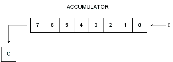
Arithmetic Shift Left
As you can see from this illustration, the instruction ASL moves each bit in an 8-bit number one space to the left, each bit except Bit 7. Bit 7 drops into the carry bit of the processor status (P) register. The ASL instruction is used for many purposes in 6502 assembly language. You could use it as an easy way of doubling a number.
10 ;
20  *=$0600
30 ;
40  LDA #$40; REM 0100 0000
50  ASL A; SHIFT VALUE IN ACCUMULATOR TO LEFT
60  STA $CB
70  .END
If you run this program, and then use your debugger’s “D” (display) command to examine the contents of memory address $CB, you’ll see that the number $40 90100 0000) has been doubled to $80 (1000 0000) before being stored in memory address $CB.
Packing Data Using ASL
Another use for the ASL instruction is to “pack” data, and thus to increase a computer’s effective memory capacity. To get an idea of how data packing works, suppose you had a series of 4-byte values stored in a block of memory in your computer. These values could be ASCII characters, BCD numbers, (more about those later) or any other kind of 4-bit values. Using the ASL instruction, you could pack two such values into every byte of the block of memory in which they were stored. You could thus store the values in half the memory space that they had previously occupied in their unpacked form. Here is a routine you could use in a loop to pack each byte of data:
10 ;
20 ;PROGRAM FOR PACKING DATA
30 ;
40  *=$0600
50 ;
60 NYB1=$C0
70 NYB2=$C1
80 PKDBYT=$C2
90 ;
0100  LDA #$04
0110  STA NYB1
0120  LDA #$06
0130  STA NYB2
0140 ;
0150  CLC
0160  LDA NYB1
0170  ASL A
0180  ASL A
0190  ASL A
0200  ASL A
0210  ADC NYB2
0220  STA PKDBYT
0230  .END
Download / View (Assembly source code)
How the Routine Works
This routine will load a 4-bit value into the accumulator, shift that value to the high nibble in the accumulator, and then use the instruction ADC to place another 4-bit value in the low nibble of the accumulator. The accumulator is this “packed” with two 4-bit values, and those two values are then stored in a single 8-byte memory register.
Testing the Results
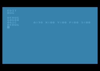
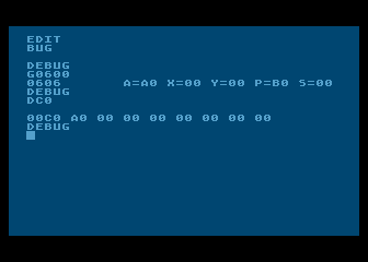
Type the program into your computer, and you can then use MAC/65 or Atari debugger’s G (GOTO) command to run it. Then, if it executes correctly, you can use your debugger’s “D” (display) command to see exactly what has been done. With your assembler in its DEBUG mode, type “DC0” and you should see this line:
00C0 04 06 46 00 00 00 00 00
As you can see from this line, the program has stored the number $04 in memory address $C0, and $06 in memory address $C1. Both of these values have been packed into memory address $C1. It doesn’t take much imagination to see how this technique can double your computer’s capacity to store 4-bit numbers in 8-bit memory locations.
Unpacking Data
It wouldn't do any good to pack data if it couldn't later be unpacked. It so happens that data packed using ASL can be unpacked using a complementary instruction, LSR (logical Shift Right). We'll discuss the LSR instruction later on in this chapter.
Loading a Color Register Using ASL
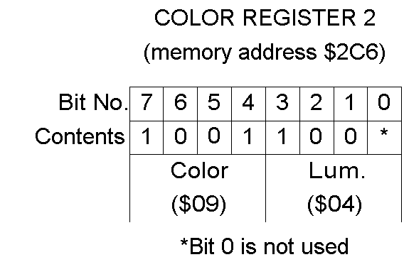
In Atari assembly language, the ASL command can also be used to control the colors on the screen. Here's how that's done. In an Atari computer the colors you can use in screen graphics are stored in five color registers. Tables listing the colors and luminance values that can be stored in these registers are printed in Part 9 of the Atari BASIC Reference Manual. The upper nibble of each Atari color register holds a hue value, which is the same number as the second parameter used in the SETCOLOR command in Atari BASIC. Bits 1, 2 and 3 in each color register hold the luminance value of the color, the same number as the third parameter in the BASIC SETCOLOR command. It doesn't matter what bit 0 is in a color register, since that bit is not used. By using the instruction ASL, you can easily control the onscreen colors in an Atari assembly language program.
How it's Done
Color Register 2 holds the background color in Graphics 0, the standard Atari text mode. Suppose you wanted to load this register with its standard color, which is light blue. In your Atari, the memory address of Color Register 2is $02C6. The Atari code number for blue is 9, and the code number for the luminance of the light blue used in the Graphics 0 screen display is 4. The ASL command could therefore be used to store light blue in Color Register 2 in the following manner:
10 ;
20 ; SETCLR PROGRAM
30 ;
40  *=$0600
50 ;
60  CLC
70  CLD
80  LDA #$09; REM LIGHT BLUE
90  ASL A
0100  ASL A
0110  ASL A
0120  ASL A
0130  STA $02C6; REM COLOR REGISTER 2
0140  LDA #$04; HUE NO. 4
0150  ASL A
0160  ADC $02C6
0170  STA $02C6
0180  .END
Download / View (Assembly source code)
As you can see, this program loads Color Register 2 (address $02C6) with Color #$09, Luminance #$04, the shade of light blue that Atari uses for the background of its standard Graphics 0 screen. If you assemble the program and run it, these are the values that will wind up in each bit of Color Register 2 (memory address $02C6) in your computer.
Testing the Program
Type the program and execut it, you can then use the "D" command of your MAC/65 or Atari debugger to see if it worked. When you type "D26C" take a look at the contents of Color Register 2, your display line should tell you that memory address $2C6 (Color Register 2) contains the value $98 Convert the hex number $98 to a binary number, and you'll see that it equals 10011000, the exact binary number illustrated above in our bit-by-bit breakdown of Color Register 2. This same technique could also be used, to load any other register with any other color and luminance in an assembly language program. Here's one way the program could be rewritten to make it more versatile:
A Better Program For Setting Colors
10 ;
20 ; SETCLR PROGRAM
30 ;
40 CLRNR=$C0; COLOR NUMBER
50 HUENR=$C1; HUE NUMBER
60 CLREG=$2C6; COLOR REGISTER NR.
70 ;
80  *=$0600
90 ;
0100  LDA #$09; LIGHT BLUE
0110  STA CLRNR
0120  LDA #$04; HUE #4
0130  STA HUENR
0140 ;
0150  CLC ; CLEAR CARRY FLAG
0160  CLD ; CLEAR DECIMAL FLAG
0170  LDA CLRNR
0180  ASL A
0190  ASL A
0200  ASL A
0210  ASL A
0220  STA CLREG
0230  LDA HUENR
0240  ASL A
0250  ADC CLREG
0260  STA CLREG
0270  .END
Download / View (Assembly source code)

SETCLR.SRC
This is actually two programs in one. In line 100 to 130, you can stuff values you want to use into variables that represent a color, a luminance, and a color register. Then the main body of the program, lines 150 through 260, can be used to load any color and luminance values into any color register. So why not try it? Change the variables we used in lines 40 through 60, run the program a few times, and watch the colors on your screen change!
An Easier Way
You can also change the screen colors generated by your Atari without going to the trouble of using a lot of ASL commands. If you wish, you can perform all of the necessary ASL operations in your head, before writing the program. For example, if you multiply on of Atari's color numbers by $10 (or 16 in decimal notation), you'll get the same result that you would if you performed four ASL operations on the number. Multiply $09 by $10, and you'll get $90, the same number you'd get by performing four ASL operations on the number $09. Similary, you can perform one ASL operation on a binary number by simply multiplying it by 2 (or, if you prefer, by $02). Perform one ASL operation on the number $04 (binary 0100), and you get $08 (binary 1000); the same number you'd get if you multiplied $04 by 2. If you wanted to write an easier SETCLR program, you could do it this way:
AN EASIER SETCLR PROGRAM
ESETCLR.SRC
10 ;
20 ; AN EASIER SETCLR PROGRAM
30 ;
40 CLRNR=$C0 ; COLOR NUMBER
50 HUENR=$C1 ; HUE NUMBER
60 CLREG=$2C6 ; COLOR REGISTER NO.
70 ;
80  *=$0600
90 ;
0100  LDA #$90; COLOR NO. 09 TIMES $10
0110  STA CLRNR
0120  LDA #$08 ; HUE NO. 04 TIMES 2
0130  STA HUENR
0140 ;
0150  CLC ; CLEAR CARRY FLAG
0160  CLD ; CLEAR DECIMAL FLAG
0170  LDA CLRNR
0200  STA CLREG
0230  LDA HUENR
0250  ADC CLREG
0260  STA CLREG
0270  .END
Download / View (Assembly source code)
ESETCLR.SRC
By adding a couple of loops to a program like this, plus an infinite loop at the end, it would be possible to stuff a color register with a constantly changing rainbow of colors. You could then make the Atari computer cycle over and over again through all of its screen colors, not stopping until someone hit the BREAK or SYSTEM RESET key, or turned off the machine or pulled the plug. Here's a program that will do just that. It will loop endlessly through all of the colors and hue combinations that your Atari can generated, displaying each of them in turn on the border area around your computer screen. (If the program looks familiar, that's because it is. As promised, it's an assembly language version of the BASIC color rotation program that was presented back in Chapter 2.)

THE ATARI RAINBOW
RAINBOW.SRC
10 ;
20 ; RAINBOW.SRC
30 ;
40 COLRBK=$2C8; THE GRAPHICS 0 BORDER COLOR REGISTER
50 TMPCLR=$C0; A PLACE TO STORE COLORS TEMPORARILY
60 ;
70  *=$0600
80 ;
90 START LDA #$FE ; MAX COLOR VALUE
0100  STA TMPCLR
0110 ;
0120 NEWCLR LDA TMPCLR
0130  STA COLRBK
0140 ;
0150  LDX #$FF
0160 LOOPA NOP; JUST A DELAY LOOP
0170 ;
0180  LDY #$30
0190 LOOPB NOP; ANOTHER DELAY LOOP
0200  DEY ; DECREMENT Y REGISTER
0210  BNE LOOPB
0220 ;
0230  DEX ; DECREMENT X REGISTER
0240  BNE LOOPA
0250 ;
0260  DEC TMPCLR ; DCREMENT TMPCLR
0270  DEC TMPCLR ; SUBTRACT 2 FOR NEXT COLOR
0280  BNE NEWCLR ; IF NOT ZERO, CHANGE COLORS AGAIN
0290 ;
0300  JMP START; ALL COLORS DISPLAYED - NOW DO 'EM ALL AGAIN
Download / View (Assembly source code)
LSR (Logical Shift Right
The instrution LSR (Logical Shift Right) is the exact opposite of the instruction ASL, as you can see from this illustration:
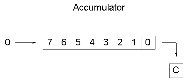
An Illustration Of The "LSR" Mnemonic
How The LSR Instruction Works
LSR, like ASL, works on whatever binary number is in the 6502's accumulator. But it will shift each bit in the number one position to the right. Bit 7 of the new number, left empty by the LSR instruction, will be filled in with a zero. The LSB (Least Significant Bit) will be dumped into the carry flag of the P register. The LSR instructrion can be used to divide any even 8-bit number by 2, as follows:
DIVIDING A NUMBER BY 2 WITH THE "LSR" INSTRUCTION
DIV2LSR.SRC
10 ; DIV2LSR.SRC
20 ; DIVIDING BY 2 USING LSR
30 ;
40 VALUE1=$C0
50 VALUE2=$C1
60 ;
70  *=$0600
80 ;
90  LDA #6
0100  STA VALUE1
0110 ;
0120  LDA VALUE1
0130  LSR A
0140  STA VALUE2
0150  .END
Download / View (Assembly source code)
This routine can also be used for another purpose. If you run it, and then check the carry flag, you cann tell whether the number in VALUE1 is odd or even. If the routine leaves the carry bit clear, the number that was just divided is odd. If the carry bit is set, the value is even!
Next is a program you can type, execute, and check using your debugger to see whether a number is even or odd. If the program leaves the number $FF in memory address $C2, labeled FLGADR, then the number divided by 2 in line 160 is odd. If the program leaves a 0 in FLGADR, then the number that was divided is even:
10 ; ODDEVEN.SRC
20 ; ODD OR EVEN?
30 ;
40 VALUE1=$C0
50 VALUE2=$C1
60 FLGADR=$C2
70 ;
80  *=$0600
90 ;
0100  LDA #7; (ODD)
0110  STA VALUE1
0120  LDA #0
0130  STA FLGADR; CLEARING FLGADR
0140 ;
0150  LDA VALUE1
0160  LSR A; PERFORM THE DIVISION
0170  STA VALUE2; DONE
0180 ;
0190  BCS FLAG
0200  RTS; END ROUTINE IF CARRY CLEAR
0210 ;
0220 FLAG NOP;
0230  LDA #$FF; OTHERWISE,SET FLAG
0240  STA FLGADR
0250  RTS; ... AND END PROGRAM
Download / View (Assembly source code)
Unpacking Data
As we've mentioned, you can also use LSR to unpack data that has been packed using ASL. But to unpack data, you also have to use another type of assembly language function, called a logical operator. We'll discuss logical operators and present a sample routine for unpacking data later in this chapter. Meanwhile, let's take a look at two more bit-sifting operators: ROL (which stands for "ROtate Left") and ROR (which means "ROtate Right).
ROL (Rotate Left) and ROR (Rotate Right)
The instruction ROL (rotate left) and ROR (rotate right) are also used to shift bits in binary numbers. But they don't make use of the carry bit. Instead, they work this way:
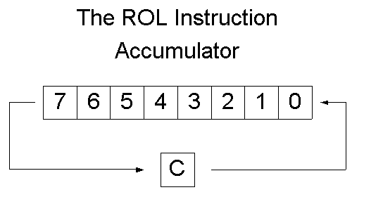
The ROL ("Rotate Left") Instruction
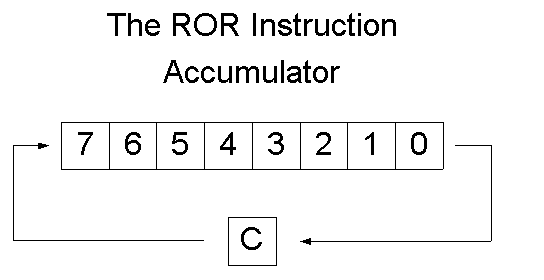
The ROR ("Rotate Right") Instruction
How "ROL" And "ROR" Work
As you can see, ROL and ROR work much like ASL and LSR, except that the carry bit is shifted into the end bit left empty by the rotation instead of zero. ROL, like ASL, shifts the contents of a byte one place to the left. But ROL does not place a zero into bit 0. Instead, it moves the carry bit into bit 0 of the number being shifted, which has been left empty by the shift rotation, and places bit 7 into the carry bit. ROR works just like ROL, but in the opposite direction. It moves each bit of a byte right one position, placing the carry bit into bit 7 and bit 0 into the carry bit.
The Logical Operators
Before we move on to conventional binary arithmetic, let's take a brief glance at four important assembly language mnemonics called logical operators. These instructions are AND ("and"), ORA ("or"), EOR ("exclusive or"), and BIT ("bit"). The four 6502 logical operators look very mysterious at first glance. But, in typical assembly language fashion, they lose much of their mystery (and most of their scare value) once you understand how they work.
AND, ORA, EOR and BIT are all used to compare values. But they work differently from the comparison operators CMP, CPX and CPY. The instructions CMP, CPX and CPY all yield very general results. All they can determine is whether two values are equal and, if the values aren't equal, which one is larger than the other. AND, ORA, EOR and BIT are much more specific instructions. They're used to compare single bits of numbers, and hence have all sorts of uses.
Boolean Logic
The four logical operators in assembly language use principles of a mathematical science called Boolean Logic. In Boolean logic, the binary numbers 0 and 1 are used not to express values, but to indicate whether a statement is true or false. If a statement is proved true, its value in Boolean logic is said to be 1. If it is false, its value is said to be 0. In 6502 assembly language, the operator AND has the same meaning that word "and" has in English. If one bit AND another bit have a value of 1, and are thus "true," then the AND operator also yields a value of 1. But if any other condition exists, if one bit is true and the other is false, or if both bits are false, then the AND operator returns a result of 0, or false.
The results of logical operators are often illustrated with diagrams called truth tables. here's a truth table for the AND operator.

In 6502 assembly language, the AND instruction is often used in an operation called bit masking. The purpose of bit masking is to clear or set specific bits of a number. The AND operator can be used, for example, to clear any number of bits by placing a zero in each bit that is to be cleared. This is how that kind of bit masking operation could work:
100  LDA #$AA; BINARY 1010 1010
110  AND #$F0; BINARY 1111 0000
MASKING.SRC
If you computer encountered this routine in a program, the following AND operation would take place:
    1010 1010 (contents of accumulator
AND 1111 0000
-------------
    1010 0000 (new value in accumulator
As you can see, this operation would clear the low nybble of $AA to $0 (with a result of $A0). The same technique would work with any other 8-bit number. No matter what the number being passed through the mask 1111 0000 might be, its lower nybble would always emerge from the AND operation unchanged.
Unpacking Data Using the "AND" Operator
The AND operator, together with the bit-shifting instruction LSR, can be used to unpack data that was packed using the instruction ASL. Here is a sample routine for unpacking data.
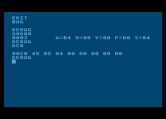
10 ;
20 ; UNPACKING DATA
30 ;
40 PKDBYT=$C0
50 LONYB=$C1
60 HINYB=$C2
70 ;
80  *=$0600
90 ;
0100  LDA #$45; OR ANYTHING ELSE
0110  STA PKDBYT
0120  LDA #0; CLEAR LONYB AND HINYB
0130  STA LONYB
0140  STA HINYB
0150 ;
0160  LDA PKDBYT
0165  PHA; SAVE IT ON THE STACK
0170  AND #$0F; BINARY 0000 1111
0180  STA LONYB; LOW NYBBLE
0190  PLA; PULL PKDBYT OFF THE STACK
0200  LSR A
0210  LSR A
0220  LSR A
0230  LSR A
0240  STA HINYB; HIGH NYBBLE
0250  RTS
Download / View (Assembly source code)
Unpacking Data With UNPACK.SRC
The "ORA" Operator
When the instruction ORA ("or") is used to compare a pair of bits, the results of the comparison is 1 (true) if the value of either bit is1. Here is the truth table for ORA:
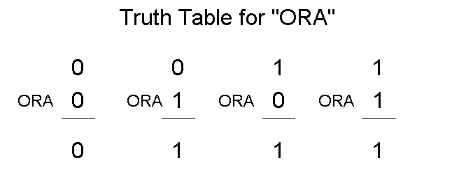
ORA is also used in bit masking operations. Here is an example of a masking routine using ORA:
LDA #VALUE
ORA $0F
STA DEST
Suppose that the number in VALUE were $22 (binary 0010 0010). The following is the masking operation that would then take place.
    0010 0010 (in accumulator)
ORA 0000 1111
-------------
    0010 1111 (new value in accumulator)
The "EOR" Operator
The instruction EOR ("exclusive or") will return a true value (1) if one, and only one, of the bits in the pair being tested is a 1. The following truth table is for the EOR operator.
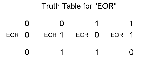
The EOR instruction is often used for comparing bytes to determine if they are identical, since if any bit in two bytes is different, the result of a comparison will be non-zero. Here is an illustration of that comparison.
Example 1             Example 2
     1011 0110             1011 0110
 EOR 1011 0110    but: EOR 1011 0111
------------------------------------
     0000 0000             0000 0001
In Example 1, the bytes being compared are identical, so the result of the comparison is zero. In Example 2, one bit is different, so the result of the comparison is non-zero. The EOR operator is also used to complement values. If an 8-bit value is used with $FF, every bit in it that's a 1 will be complmented to a 0, and every bit that's a 0 will be complmented to a 1.
    1110 0101 (in accumulator)
EOR 1111 1111
-------------
    0001 1010 (new value in accumulator)
Still another useful characteristic of the EOR instruction is that when it is performed twice on a number using the same operand, the number will first be changed to another number, and then restored to its original value. This is shown in the following example.
    1110 0101 (in accumulator)
EOR 0101 0011
-------------
    1011 0110 (new value in accumulator)
EOR 0101 0011 (same operand as above)
-------------
    1110 0101 (original value in accumulator restored)
This capability of the EOR instruction is often used in high resolution graphics to put one image over another without destroying the one underneath. (Yes, that's how its done!)
The "BIT" Operator
That brings us to the BIT operator, an instruction even more esoteric than AND, ORA, or EOR. The BIT instruction is used to determine the state of a specific bit - or specific bits - of a binary value stored in memory. When the BIT instruction is used in a program, bits 6 and 7 of the value being tested are transferred directly to bits 6 and 7 (the sign and overflow bits) of the processor status register. Then and AND operation is performed with the accumulator and the value in memory. The result of this AND operation is stored in teh Z(zero) flag of the P register. If there is a 1 in both the accumulator and the value in memory at the same bit position, the result is non-zero and the Z flag is cleared. If the bits are different or both zero, the result is zero and the Z flag is set. The most important aspect here is that after all of this takes place, the values in the accumulator and the memory location remain unchanged.
Return to Table of Contents | Previous Chapter | Next Chapter
