PAGES
TWO THROUGH FOUR
Locations 512 to 1151, as you will see, are used by the OS as a workspace. Some are used for variables, some for tables, some for vectors, some for buffers, and some just for miscellaneous stuff. Now, a few words on using these locations. Don't, unless the description says you can! A lot of them are very important to the OS, and if you mess with them they may cause the computer to crash, which you don't want to happen. Keep in mind, though, that no matter what you do you can't hurt the computer (unless you throw it at a wall in frustration). You'll just hurt your program.
Also, be careful of locations that don't appear to be used. Atari has warned that these locations may be used in future versions of the OS, so stay away if you want to make sure your programs will work on all machines.
Let's jump right into page two. The first 42 bytes are used for interrupt vectors, so we'd better take a quick look at interrupts. As you remember, we first saw interrupts at location POKMSK (16). If you don't remember, go back and re-read that section. I'll wait for you here.

Back again? OK, so now we have the basic idea of what an interrupt is. The type of interrupt we saw at POKMSK is called an Interrupt ReQuest (IRQ). There's another kind of interrupt called a Non-Maskable Interrupt (NMI). What's the difference? Well, there's an assembly language command called SEI (SEt Interrupt disable). It tells the 6502 (the main chip) to ignore IRQ-type interrupts. Unfortunately, it can't tell the 6502 to ignore the NMIs. They are taken care of by another chip, called ANTIC, and so ANTIC is where you must go if you want to ignore NMIs.
The NMIs consist of the Vertical Blank Interrupt (VBI), the Display List Interrupt (DLI), and the SYSTEM RESET interrupt. We'll be seeing the interrupt vectors for both IRQs and NMIs in the next few locations, along with how to use them. An interrupt vector tells the OS where to go when the corresponding interrupt occurs (assuming it hasn't been disabled).
You might also want to look at IRQEN (53774), NMIEN (54286), and NMIST (54287) for more information on interrupts.
VDSLST
512,513 0200,0201
This is the vector for the Display List Interrupt (DLI) which is an NMI as we discussed in the last location. DLIs interrupt the screen drawing process so you can do things like change the screen color halfway down. They exist entirely for your benefit, the OS doesn't use them at all.
To get a DLI going, there are a couple of things you have to do. First, and most important, you have to decide what you want the interrupt to do! Write the routine to do it, making sure it ends with an RTI (ReTurn from Interrupt) instruction. Next, decide which row on the screen you want it to occur at (it will actually occur at the end of this row). Go into the display list and set the leftmost bit (bit seven) of the instruction for that row. That tells the display list that there is to be a DLI on this row. Now tell the OS where the DLI routine is by setting VDSLST (low byte and high byte of the routine address). Finally, you have to enable the DLIs. Do this by setting NMIEN (54286) to 192.
Here's a quick example from BASIC, simply reversing the playfield colors halfway down the screen:
100 GRAPHICS 0
110 DLIST=PEEK(560)+PEEK(561)*256
120 POKE DLIST+16,130
130 FOR MEM=1536 TO 1553
140 READ INSTR
150 POKE MEM,INSTR
160 NEXT MEM
170 POKE 512,0:POKE 513,6:POKE 54286,192
180 LIST
190 DATA 72,173,198,2,141,10,212,141,23,208
200 DATA 173,197,2,141,24,208,104,64
110 DLIST=PEEK(560)+PEEK(561)*256
120 POKE DLIST+16,130
130 FOR MEM=1536 TO 1553
140 READ INSTR
150 POKE MEM,INSTR
160 NEXT MEM
170 POKE 512,0:POKE 513,6:POKE 54286,192
180 LIST
190 DATA 72,173,198,2,141,10,212,141,23,208
200 DATA 173,197,2,141,24,208,104,64
Make sure that the DATA is correct before you run the program. If it isn't, the computer might lock up. Here's an assembly listing of what those DATA statements represent:
0600 48
PHA
0601 ADC602 LDA COLOR2
0604 8D0AD4 STA WSYNC
0607 8D17D0 STA COLPF1
060A ADC502 LDA COLOR1
060D 8D18D0 STA COLPF2
0610 68 PLA
0611 40 RTI
0601 ADC602 LDA COLOR2
0604 8D0AD4 STA WSYNC
0607 8D17D0 STA COLPF1
060A ADC502 LDA COLOR1
060D 8D18D0 STA COLPF2
0610 68 PLA
0611 40 RTI
Now that you know the basics, let me tell you a few limitations. First of all, there is very little time available during a DLI before the next row starts to get drawn. Make your routine short. Second, because an interrupt often occurs while something else is going on (like your BASIC program running), you have to make sure that you restore the accumulator and the X and Y registers if you use them. Do this by pushing their values onto the stack before you use them, and then pulling the values back off before you RTI. Finally, as should be painfully obvious to you BASIC programmers by now, this is most definitely machine language country. It's not very difficult machine language, but it is machine language.

A few notes now for the machine language programmers. Change the hardware registers, not the shadow registers. The shadow registers are used to update the hardware registers during VBLANK, so changing them halfway down the screen won't have any effect until VBLANK kicks in.
If you're going to have more than one DLI, then each DLI routine will have to reload VDSLST to point to the next one. The last one will have to point back to the first one. Make sure in this case that you enable the DLIs during VBLANK, or else they may not execute in the right order.
Use WSYNC (54282) if you're changing screen colors. When any value is stored in WSYNC, the next command won't be executed until the TV has finished drawing the current scan line. If you don't use it, your colors will change in the middle of a line and will flicker back and forth. Try it and see for yourself (get rid of "141,10,212" in line 190 and change "1553" in line 130 to "1550").
One other problem with DLIs is that pressing a key on the keyboard can cause DLI colors to "jump" down a scan line (try it). The solution? Well, the easiest is just not to use the keyboard. For more complex ways around it, you should consult De Re Atari.
DLIs are extremely powerful. They can be used to change colors, to change character sets, even to change player/missile positions and the fine scrolling registers, so be creative. Proper use of DLIs can produce a program that will do things you never thought the Atari was capable of.
VPRCED
514,515 0202,0203
This one's an IRQ vector, for an interrupt called the "serial proceed line interrupt," where the word "serial" indicates I/O to a peripheral such as the disk drive. It is initialized to 59314, which just holds a PLA and an RTI (i.e., the interrupt is not used).
VINTER
516,517 0204,0205
Another IRQ, this time for the "serial bus I/O interrupt." Initialized to 59314 again because it isn't normally used. Both VINTER and VPRCED's interrupts are processed by the PIA (Peripheral Interface Adapter) chip.
VBREAK
518,519 0206,0207
IRQ again, for the machine language BRK command [which is not the same as the BREAK key; see POKMSK (16) and BRKKEY (17)]. It's also initialized to 59314.
VKEYBD
520,521 0208,0209
From now on, if I don't tell you what kind of interrupt it is, it's an IRQ, OK? There's a whole bunch of these suckers and only so many ways to say "here's another IRQ."
So here's another IRQ. This one occurs whenever a key other than BREAK is pressed (START, OPTION, and SELECT don't count because they're buttons, not keys). It's initialized to 65470 which is the OS keyboard IRQ routine (it makes sure that only one character gets printed when you press a key, and resets ATRACT [77]). If you want to put your own routine in, this is the place to do it. Keep in mind, however, that your routine will be executed before the key code gets converted to ATASCII (see the OS manual for a list of key codes).
The following three vectors are used to control communication between the serial bus and the serial bus devices (serial refers to the fact that bits are sent or received one after the other in succession). A much simplified expanation of this process follows. You should consult De Re Atari if you need more details.
The data being sent or received is stored in a buffer. If we're doing output, then a byte gets transferred from the buffer over to the serial output register (an interrupt routine does this). SIO takes it from there and puts it in POKEY's serial output shift register. POKEY then picks it up and sends it out one bit at a time. An interrupt is then generated and the whole process starts over. This goes on until the checksum byte has been sent, at which time a "transmit done" interrupt is generated and SIO hands control back to the main program, which has been waiting patiently all this time.
The process is pretty much the same if we're receiving data, except in reverse.
VSERIN
522,523 020A,020B
This is a good one. The "POKEY serial I/O bus receive data ready" interrupt vector. It means that this vector is used when the I/O bus indicates that it has received a byte that is now waiting in the serial input register, ready to be moved to a buffer. The routine in the OS to do this is at 60177, and that's what VSERIN is initialized to.
VSERIN is also called INTRVEC by DOS, which changes its value to 6691, a routine in DOS that does pretty much the same thing as the one in the OS, except in a different place.
VSEROR
524,525 020C,020D
The opposite of VSERIN, VSEROR is used when the I/O bus is ready to send a byte. Its official name is the "POKEY serial I/O bus transmit data ready" interrupt vector, which should make more sense this time. It is initialized to 60048, the address of an OS routine that, logically, moves the next byte in the buffer to the serial output register (from whence it gets sent). DOS messes with this one too, changing it to 6630, the address of its routine to do the same thing.
VSEROC
526,527 020E,020F
Another long-winded name: the "POKEY serial I/O bus transmit complete" interrupt vector. Since I'm sure you're all becoming experts at interpreting these names, it should come as no surprise that this vector is used when all the data has been sent. It is initialized to 60113, a routine that, when the checksum byte is sent (see CHKSUM [49]), sets the "transmission" done flag at XMTDON (58) and disables this kind of interrupt.
The following three locations are the interrupt vectors for the POKEY timers, all of which are initially unused and therefore set to the PLA/RTI combination at location 59314. The timer interrupt occurs when the associated timer counts down to zero.
For more information on the POKEY timers, see the section on timers right before location 53760.
VTIMR1
528,529 0210,0211
Interrupt vector for POKEY timer one (see AUDF1 [53760,53761]).
VTIMR2
530,531 0212,0213
Interrupt vector for POKEY timer two (see AUDF2 [53762,53763]).
VTIMR4
532,533 0214,0215
Interrupt vector for POKEY timer four (see AUDF4 [53766,53767]). This vector only exists in the "B" version of the OS.
VIMIRQ
534,535 0216,0217
Every IRQ vectors through this location on its way to the individual interrupt routines. It is initialized to 59126, the address of an OS routine that looks at IRQST (53774) to determine what kind of interrupt occurred and then jumps through the appropriate vector.
Attention B OS owners!
Since a lot of addresses in the new "B" version of the OS got shifted around, some of the initialization addresses given aren't the same in that version (which is now in a majority of the Atari's out there). Here are the changes (Figure 9).
Software timers
There are two types of timers in the Atari: software and hardware. We've already come across the hardware timers (see VTIMR1-4 [528-533]) and we're about to learn everything we never wanted to know about the software timers, which use locations 536 to 558. But first, a few words from our author.
There are, of course, differences between software and hardware timers, and you'll probably want to know them before you go running off into timer land. The biggest difference comes from the names.
| VECTOR VDSLST VPRCED VINTER VBREAK VKEYBD VSERIN VSEROR VSEROC VTIMR1-4 VIMIRO VVBLKI VVBLKD |
INITIAL VALUE 59280 59279 59279 59279 same as before 60175 same as before 60111 59279 59142 59310 59653 |
FIGURE 9. Vector list
Hardware timers are built into the POKEY chip, software timers are a part of RAM. The big difference comes in the way they keep time. You recall from location RTCLOK (18-20) that a jiffy is a sixtieth of a second, the amount of time it takes the television set to fill the screen. Well, the software timers count down by one every jiffy. The hardware timers, on the other hand, count down by an amount less than a jiffy, which you can specify (see locations 53760 through 53769). So, if you want to time things that take longer than a jiffy, use the software timers. Otherwise, go for the hardware.
CDTMV1
536,537 0218,0219
This is the first software timer (affectionately known as "system timer one"). Every VBLANK, the value in CDTMV1 gets decremented by one. When it reaches zero, a flag gets set so the OS knows to JSR through CDTMA1 (550,551). An important thing to note here is that the decrementing for this timer (and only this timer) is done during state one VBLANK. This means that CDTMV1 (along with RTCLOK [18-20] and ATRACT [77]) is updated every VBLANK, no matter what's going on elsewhere in the computer. The rest of the software timers, on the other hand, are updated during stage two, which means that during time-critical I/O (like disk and cassette I/O; see CRITIC [66]), the other timers are not updated. Unfortunately, the OS knows this too, so it uses CDTMV1 for I/O routines. So, you see, we have a catch-22 situation here. Oh well! If you're doing your own time critical routines though, you know which timer to use.
CDTMV2
538,539 021A,021B
This is system timer two, of course. When it reaches zero, it JSR's through CDTMA2 (552,553). And, unless you slept through the last paragraph, you should already know that it will not be updated during time-critical I/O.
CDTMV3
540,541 021C,021D
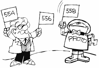
The third system timer, again hampered by time-critical I/O. This one has problems of its own though. First of all, the cassette handler uses it. Secondly instead of JSRing through a vector when it gets down to zero, it just clears a flag at CDTMF3 (554). So don't use it during cassette operations and don't expect it to go anywhere after it's done.
CDTMV4
542,543 021E,021F
Let's see. You've already figured out that this is system timer four, that it doesn't work during time-critical I/O, and you may have guessed that it clears a flag at CDTMF4 (556) when it's done instead of vectoring. What's left for me to say?
CDTMV5
544,545 0220,0221
The last of the timers. This one is no different than the last one except that the flag it clears is at CDTMF5 (558). But since you're getting to know these things so well, I shouldn't have to tell you that.
VVBLKI
546,547 0222,0223
Since this is the vector for the VBLANK interrupt (VBI), I suppose this is probably a good time to explain exactly what vertical blank is. With all the previous mentions of jiffies in this book, you should know by now that a jiffy is a sixtieth of a second. It is important because that's the time it takes the television set to fill the whole screen with a picture. Since the screen can't hold on to that picture for very long, the TV keeps drawing the picture over and over again, even if it doesn't change. It draws it one line at a time, from top to bottom. When it gets to the bottom, it stops drawing and goes back to the top, where it starts all over again. Now, the important part for us is when it stops drawing. At that time it tells the computer, "Hey, I'm not drawing to the screen anymore," thus generating a vertical blank interrupt. You should be able to see where the name comes from now. Incidentally, there is also a horizontal blank, which occurs while the TV has finished drawing one line and is on its way to the beginning of the next. Store any value in WSYMC (54282) and the computer won't do anything until the next HBLANK occurs.
Back to VBLANK. There are a few reasons why the TV isn't drawing to the screen. First of all, it gives us a way to time things, since VBLANK occurs precisely every sixtieth of a second. Secondly, nothing is being drawn to the screen during this time, so any graphics changes made during VBLANK will result in smooth, instantaneous changes on the screen. But, perhaps most importantly, VBI code runs independently of mainline code. What does that mean? It means that VBI code is essentially a separate program, running at the same time as your regular program! I wrote one VBI program, for example, that allowed the computer to play music at the same time I was typing in programs. Chris Crawford, in his classic Eastern Front 1941 game, used VBI to separate the thinking process of the game from the tedious stuff like graphics and user input. That allowed the computer to think about its next move at the same time the player was thinking about his or hers, thus simulating a true one-on-one situation. As you can see, VBLANK is an extremely powerful tool.
Let's take a closer look at what normally goes on during VBI. First of all, there are two stages. The first stage is always executed, while the second gets ignored if the time-critical I/O flag at CRITIC (66) is set. The first is called "immediate" vertical blank, the second is "deferred."
VVBLKI is the vector for the immediate stage so the OS goes through VVBLKI when the VBLANK interrupt first occurs. During this stage the realtime clock (RTCLOK [18-20]), the attract mode (ATRACT [77], DRKMSK [78], and COLRSH [79]), and system timer one (CDTMVI [536, 537]) get updated, processed, and so forth. Then CRITIC is checked. If it's set, indicating that the interrupt occurred in the middle of a time-critical I/O operation, the OS returns from the interrupt. If it's not, then it's OK to go on to stage two, so we do. When the OS is done with stage two (see the appendices for a complete list of what's done here), it vectors through VVBLKD (548,549) to the user's deferred VBI routine, and then finally returns from the interrupt when it's done there.
VVBLKI is initialized to point to SYSVBV (58463), which contains a JMP instruction to the OS stage one code (located at 59345 in the old OS, 59310 in the new one). If you change VVBLKI to point to your own routine, and you still want the OS code to be executed, you should end your routine with a JMP SYSVBV statement.
Whew, what a lot of mumbo jumbo! If you managed to plod through all of that, take a well-deserved rest. When you're done, we'll take a look at how you can use vertical blank for your own routines.

VVBLKD
548,549 0224,0225
Don't worry, there's still more to come on VBIs! This just seemed like a good time to formally introduce VVBLKD, the vector for the user's deferred VBI routine. The OS initializes VVBLKD to its "exit vertical blank" routine (at 59710 in the old OS, 59653 in the new one). If you use VVBLKD to point to your own routine, make sure to end that routine with a JMP XITVBL (XITVBL contains a JMP instruction to the exit vertical blank routine, which means you don't have to worry about which OS is being used since XITVBL is at 58466 in both). Note that you can also avoid the whole entire OS VBI code by writing your own immediate VBLANK routine and ending it with a JMP XITVBL instead of a JMP SYSVBV. Remember that none of the timers or color registers or anything will be updated if you do this (unless you update them in your routine).
By now you're probably either real excited over the prospect of using VBls yourself, or you're asleep. If it's the latter, then you're not even reading this because your eyes are closed, so I'm only going to deal with those of you who are excited, OK? Let's look at how to write our own VBLANK routines.
The first step is to decide whether you want your routine to be immediate or deferred. Most of the time it doesn't matter. There are, however, the following conditions which will require one over the other.
1. If you want to change locations that
the OS deferred routine also changes (see Appendix Ten), you obviously
want to do so after the OS does. Use deferred.
2. The maximum amount of time you can spend in immediate VBI is 2000 machine cycles (see a book on 6502 assembly language for information on the number of machine cycles per instruction). If your routine is going to be long, you should therefore put it in deferred VBI, which has 20,000 cycles available. If you don't, things are going to look mighty funny on the screen. If you do use deferred, do your graphics first, since some of those 20,000 cycles occur while the screen is being drawn.
3. If you need your routine to be executed every VBLANK, regardless of whether time-critical I/O is occurring, use immediate. Be careful, however, that your routine will not cause problems with the I/O.
Now that you've decided what it should be (and you've presumably written it and put it in memory somewhere), all you need to do is change VVBLKI or VVBLKD to point to it. A simple task, right? Not quite. What happens if a VBI occurs while you're changing the vector? Crash city!

To make sure this doesn't happen, you have to change the vectors during VBLANK. But that itself presents a small problem. How do we get into VBLANK to change the vectors if we have to change the vectors to get to VBLANK (good old catch-22 again)? Luckily, Atari has thoughtfully provided a VBI routine that makes the change for you. It's called SETVBV and is at 58460. To use it, load the 6502 Y register (LDY) with the low byte of the address for your routine, and load the X register (LDX) with the high byte. Then load the accumulator (LDA) with a six if you want immediate VBI, seven if you want deferred, and JSR SETVBV. Now your VBI will be up and running.
Here's a simple example that uses location CHACT (755) to make inverse text blink:
100 FOR MEM=1536 TO 1575
110 READ CODE
120 POKE MEM,CODE
130 NEXT MEM
140 X=USR (1536)
150 DATA 104,169,0,141,29,2,160,16,162,6,169,6,141,29,2,32
160 DATA 92,228,96,173,28,2,208,13,169,30,141,28,2,173
170 DATA 243,2,73,2,141,243,2,76,95,228
Make sure that the DATA values are correct before you run the program. If they aren't, the computer will probably crash and you'll lose the program.
Here's the assembly language listing of the machine code (which is stored in the DATA statements):
0600
68 PLA
0601 A900 LDA #$00
0603 8D1D02 STA CDTMV3 + 1
0606 A010 LDY #VBLANK&255
0608 A206 LDX #VBLANK/256
060A A906 LDA #$06
060C 8D1D02 STA CDTMV3 + 1
060F 205CE4 JSR SETVBV
0612 60 RTS
0613 AD1C02 VBLANK LDA CDTMV3
0616 D00D BNE VBLXIT
0618 A91E LDA #$1E
061A 8D1C02 STA CDTMV3
061D ADF302 LDA CHACT
0620 4902 EOR #$02
0622 8DF302 STA CHACT
0625 4C5FE4 VBLXIT JMP SYSVBV
The "LDA #$1E" in the preceding listing is used to specify a half second interval ($1E hex equals 30 decimal equals 30 jiffies equals half a second) for use in blinking. Make it larger or smaller to make the interval longer or shorter, respectively.
CDTMA1
550,551 0226,0227
CDTMA1 is the vector for system timer one (CDTMV1 [536,537]). It's initialized to 60400, which is the address of a routine to set the time out flag TIMFLG (791). This is because the OS uses CDTMV1 for I/O routines, which is a very good reason why you probably should use timer two instead.
The OS vectors through CDTMA1 when CDTMV1 counts down to zero. If you do use CDTMV1, and are setting it for a value greater than 255 (i.e., setting both the low and the high byte), this presents a potential problem. Since CDTMV1 is updated during VBLANK, and there is a chance that a VBLANK might occur while you're setting CDTMV1, you should set the low byte first. You can also use the SETVBV routine mentioned in the VBLANK description preceding. Just LDY with the low byte, LDX with the high, LDA with the timer number (1-5), and JSR SETVBV. This will assure that the timer gets set during VBLANK.
Since the OS JSRs through this vector, you should end your routine with an RTS instruction.
Incidentally, CDTMV1 reaching zero generates an NMI, which then does the vector.
CDTMA2
552,553 0228,0229
Same as CDTMA1, except this one is not used by the OS and is therefore initialized to zero. Oh, and of course CDTMV2 (538,539) reaching zero causes the vector through here, not CDTMV1. But then we already knew that, didn't we?
CDTMF3
554 022A
Unlike system timers one and two, timers three through five merely clear a flag when they count down to zero. This is the flag for CDTMV3 (540,541) and is also used by DOS as a timeout flag, so beware of possible conflicts if you use it. As with the other two flags, you must set CDTMF3 when you set CDTMV3. Any nonzero value is ok.
SRTIMR
555 022B
Well, here in the middle of all the timer stuff is a different kind of timer. As everybody knows, if you hold down a key on the Atari, it will start repeating, right? And something has to tell the OS how long to wait before starting that repeat and before repeating it again, right? And can you guess what location does that? Sure, I knew you could. SRTIMR is set to 48 every time a key is pressed. Every stage two VBLANK that the key is still held down, SRTIMR gets decremented by one. When it reaches zero, the repeat process starts. It gets set to six, decremented again, the key repeats, it gets reset to six, and so forth until the key is released. Unfortunately, there are no locations that store the two delay times, so you can't speed up or slow down the process just by changing a couple of locations. There is, however, another way to do it.
As you recall, the initial delay time of 48 is set whenever a key is pressed. As you may or may not recall, we came across a vector a few locations ago (VKEYBD [520,521]) that pointed to the IRQ routine for a key being pressed. It is in this routine that the delay is set. So, in order to change the delay, you must essentially take the OS routine, change the delay value, store your revised version in memory, and update the vector. You'll find the OS routine at location $FFBE on page 130 of the OS listing.
How about the other delay, the six jiffy one once the repeat is started? If you were paying attention (and I know you were), you already know that it gets set in stage two VBLANK. Can you guess what you're going to have to do to be able to set it yourself? If you guessed "take the OS stage two VBLANK interrupt routine and put it in my own deferred VBI routine with the delay value changed," then give yourself a pat on the back.
"But wait! The OS stage two VBI routine gets executed whether I have my own deferred VBI routine or not," you say, taking me completely by surprise. You're right though (or would have been if you had said it). Your deferred routine, however, happens after the OSs, so you can just repeat the part that sets the delay and, since you'll set it after the OS does, yours will be the one that counts. The part you want is at locations $E87C through $E897 on page 36 of the OS listing, and locations $E8E8 through $E8EE on page 37 (these locations will be different in the new OS, but that's irrelevant here). Be aware that the OS will now be executing this routine twice, and will therefore be decrementing by two every VBLANK. You should set SRTIMR to double the delay you want, and also change your deferred routine so that it resets SRTIMR if it's equal to zero or one. That makes sure that the OS routine doesn't reset it before you get a chance to.
CDTMF4
556 022C
And now, back to our timers. This is the flag for CDTMV4 (542, 543). See CDTMF3 for more information.
INTEMP
557 022D
INTEMP is used for temporary storage during the SETVBL routine. As you recall, SETVBL is at the address stored in 58460. Heaven only knows what INTEMP is doing here in the middle of the system timers.
CDTMF5
558 022E
This is the flag for CDTMV5 (558,559). See CDTMF4 for more information (ha ha).

SDMCTL
559 022F
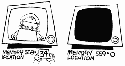
This location is amazing. So many things can be done here that you'll just flip! Maybe not. Anyway, SDMCTL controls something called Direct Memory Access (DMA). Simply put, DMA is the process by which ANTIC, the Atari graphics chip, gets the information from memory it needs to fill in the screen (this means information for the playfield and for player/missile graphics). Now this process obviously takes time and slows down the 6502 because of that. So what happens if we turn DMA off? Things will run faster. Try it; POKE 559,0 to turn DMA off. Uh-oh, what happened? The screen went blank. But of course, with no DMA, ANTIC isn't getting the information for the screen so there's no picture. What good does a computer do without a picture? Well, sometimes you don't need one. For example, if you're doing a lot of calculations, it's more important to get them done quickly than to have an "I'M THINKING" message on the screen, and turning off DMA will speed things up by as much as 30 percent! Of course, with a blank screen the user may think that the computer just up and croaked on him, so be sure you give a warning before the lights go off. SDMCTL is a shadow register for DMACTL (54272).
By the way, in case you're still sitting there after the POKE 559,0 with a lifeless computer, just press SYSTEM RESET or type in POKE 559,34. You can't see the POKE written on the screen, but it will still work when you press return.
OK, so we can turn off the screen. Big deal, right? Right, but it's what we can do when we turn the screen back on that counts. SDMCTL let's you make the playfield (the blue screen you PLOT and PRINT onto) wider, narrower, or nonexistent. It also lets you turn players and missiles on and off, define how tall you want the players to be, and, of course, turn ANTIC on and off.
Let's take a look at a breakdown of SDMCTL and see what does what (Figure 10).
To get players and missiles going, see GRACTL [53277] as well.
So, to use SDMCTL, pick the options you want, add their values, and POKE away. Note that ANTIC must be turned on if you want a display, and you can only have one type of playfield at a time. While we're on the subject of playfields, you'll probably want to know exactly what a "narrow" and "wide" playfield are. OK, here goes:
| BIT(S) |
PATTERN |
VALUE
|
RESULT |
| 0,1 |
------00 |
0 |
No
playfield |
| ------01 |
1 |
Narrow
playfield |
|
| ------10 |
2 |
Regular
playfield |
|
| ------11 |
3 |
Wide
playfield |
|
| 2 |
-----0-- |
0 |
Missiles
off |
| -----1-- |
4 |
Missiles
on |
|
| 3 |
----0--- |
0 |
Players
off |
| ----1--- |
8 |
Players
on |
|
| 4 |
---0---- |
0 |
Double
height players |
| ---1---- |
16 |
Regular
height players |
|
| 5 |
--0----- |
0 |
ANTIC
off |
| --1----- |
32 |
ANTIC
on |
|
| 6,7 |
-------- |
Not
used |
FIGURE 10. SDMCTL chart
The width of the playfield is measured by something called a "color clock." A color clock is twice as wide as a pixel in graphics mode eight. That means that a character in graphics mode zero is 4 color clocks wide (we'll use graphics mode zero as an example since you can see the playfield in this mode), and that in turn means that the regular playfield is 160 color clocks wide (forty characters times 4 color clocks per character). A narrow playfield is only 128 color clocks (32 characters) wide, while a wide playfield has 192 color clocks (48 characters). The television set draws 228 color clocks total (including the black border), but not all of these can be seen. As a matter of fact, not all of the 192 in a wide playfield can be seen either, which makes it good for horizontal scrolling.
Is having a wide or narrow playfield as easy as it sounds? Well, yes and no. Getting it on the screen's easy (try POKE 559,35 right now), using it properly isn't. Unfortunately, telling SDMCTL that you want a different size playfield doesn't tell the OS that anything's different. To see what I mean, try POKE 559,35 from graphics mode zero. Now you have 48 characters per line, but the OS still thinks you have 40. Try typing stuff in and you'll see the problem. There is no way around this problem, which means that you have to set up the screen memory yourself if you want to take advantage of this feature. Sorry.
Double-height players, in case you were wondering, have dots the height of those in graphics mode seven, while regular-height players are the height of graphics mode eight. Despite the way I named the two, double-height players are given to you unless you specify otherwise using SDMCTL.
SDLSTL
560,561 0230,0231
Another important location. SDLSTL holds the address of the display list. Let's talk display lists.
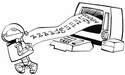
We already know about screen memory, the memory locations that hold the information that is to be displayed on the screen (see SAVMSC at 88,89). How does the computer know how to interpret this memory, though? As we learned in SDMCTL there is a special chip called ANTIC that takes care of the graphics. ANTIC has a list of commands that tells it how to display the screen memory. Oddly enough, this list is called the "display list." Since the display list is made up of commands, it's actually like a little program. And, since the screen memory has to be redisplayed 60 times a second, this program is a continuous loop, running over and over again. Why does the screen memory have to be redisplayed? The TV set draws a picture by making different parts of the screen glow at different brightnesses. The screen, however, will only glow for a very short period of time. Therefore, in order to get a picture to stay on the screen, the TV has to draw it 60 times a second.
For now, let's pretend that a display list is written just like a BASIC program, only with special commands. Let's look at what such a display list would look like:
100 DRAW 8 BLANK SCAN LINES
110 DRAW 8 BLANK SCAN LINES
120 DRAW 8 BLANK SCAN LINES
130 CHARACTER MODE 0 LINE. . .
140 ... WITH SCREEN MEMORY STARTING AT <address>
150 CHARACTER MODE 0 LINE
160 CHARACTER MODE 0 LINE
.
.
.
370 CHARACTER MODE 0 LINE
380 GOTO 100 AND WAIT FOR VBLANK
We start by telling ANTIC to leave the first 24 scan lines blank. Scan lines are the height of a graphics mode eight line, start before the left edge of the screen and go all the way past the right edge. If you look closely at the screen you can even see them. We leave 24 lines blank so that we can be sure that all of our picture will be on everyone's screen. TV and monitor screens all act slightly differently, so the blank lines will create a frame that can cover the edges of the screen. These blank lines make up the top of the black border that you can see in graphics mode zero.
Next we want to start our mode zero lines, so we have a mode zero line command. ANTIC has to know where the screen memory is before it can start drawing, so we make the first mode zero command a special one that tells ANTIC that the address of the screen memory will come next. Then, after the screen memory address, we have 23 regular mode zero commands. Finally, we tell ANTIC to go back to the beginning and start all over again after VBLANK. Remember that VBLANK is the time during which the TV is getting ready to start drawing the picture again. We want to make sure it's ready before ANTIC starts again, we so tell ANTIC to wait until VBLANK is over.
Now that we have a basic understanding, let's look at the specifics. First of all, ANTIC doesn't use line numbers. In a real display list, the line numbers would be memory locations. Secondly, ANTIC has abbreviations for all the commands. And thirdly, there is no thirdly. Let's therefore look at the proper way to write the preceding display list (we'll have it start at location 1000 [decimal], although it would usually be much higher in memory):
1000 BLK 8
1001 BLK 8
1002 BLK 8
1003 CHR 2 LMS
1004 < screen memory low byte >
1005 < screen memory high byte >
1006 CHR 2
1007 CHR 2
.
.
.
1028 CHR 2
1029 JVB 1000
1001 BLK 8
1002 BLK 8
1003 CHR 2 LMS
1004 < screen memory low byte >
1005 < screen memory high byte >
1006 CHR 2
1007 CHR 2
.
.
.
1028 CHR 2
1029 JVB 1000

As you can see, this isn't that much different from our original. LMS, by the way, stands for Load Memory Scan and tells ANTIC that the next two bytes will be the address of the beginning of screen memory. Now, the final step is to convert these commands into numbers that we can POKE into memory. There is a unique number assigned to each command, and the chart in Appendix Twelve gives you those numbers. Before you look at that chart, however, let me explain the other commands that you'll see there:
MAP is the same as CHR, except it's used to indicate a graphics mode rather than a character (text) mode.
JMP is like JVB, except it doesn't tell ANTIC to wait for the end of VBLANK. It's needed because of a quirk in ANTIC that says a display list can't cross a 1K boundary. What's a 1K boundary? It's a memory location that's a multiple of 1024. With display lists created by GRAPHICS commands, this is no problem. If you're designing your own, however, and you have to cross such a boundary, JMP over it. While we're on the topic of boundaries, you should also be aware that screen memory is not allowed to cross a 4K boundary. If it does, you have to have a second LMS instruction to get past the boundary. Under normal circumstances, however, this only happens in graphics modes 8 through 11, and the OS will take care of it for you.
HSC, like LMS, is not really a command but rather a modification to a command. It tells ANTIC that this mode line is to have the capability of fine horizontal scrolling (see HSCROL at 54276).
VSC, you guessed it, is another modification that specifies a fine vertical scrolling capability. See VSCROL (54277).
DLI is the fourth modification, telling ANTIC that there is to be a display list interrupt at the end of this mode line. Pay particular attention to the "end." See VDSLST (512,513) for more details on DLIs.
Now that you'll be able to understand the chart, why don't you go take a quick peek at it.
Run the following program to take a look at the actual graphics mode zero display list as it is stored in memory:
100 GRAPHICS 0
110 DLIST=PEEK(560)+PEEK(561)*256
120 PRINT PEEK(DLIST)
130 IF PEEK(DLIST)<>65 THEN DLIST=DLIST+1:GOTO 120
140 PRINT PEEK(DLIST+1)
150 PRINT PEEK(DLIST+2)
160 END
Use CTRL-1 to pause the display list. Notice that the last two numbers PRINTed (the address for the JVB) are the same as the values in 560 and 561. If you can't figure out why, drink a couple of cups of coffee and read this whole description all over again. Here is a hint: They tell the computer to go back and use the same display list all over again. If you change the numbers here the computer will use another display list at the new address, which means you could use several display lists at once.
We've pretty much covered the standard GRAPHICS display lists, but what about custom ones? It should have occurred to you by now that you can write your own display lists, mixing different graphics modes on the screen. Since this is true, and is such a popular thing to do, there is a special appendix at the end of the book telling you just how to do it. So please consult it if you want to write your own display list.
A few (more) words before we move on. What can you use LMSs for other than to tell ANTIC where the screen memory is? Nothing! You can, however, tell ANTIC where the screen memory is more than once in the same display list. Why would you want to do that? Well, you have to if you're fine scrolling (see HSCROL and VSCROL). You could also do it to repeat the same line over and over again without wasting memory. LMSs are another powerful tool that have no steadfast rules about what to use them for; use your creativity. Here's an example of repeating text. After the program has run, clear the screen and try typing in a line of text.
100 GRAPHICS 0
110 DLIST=PEEK(561)*256+67:POKE 560,67
120 LOW=PEEK(88)
130 HIGH=PEEK(89)+2
136 POKE 89,HIGH
137 POKE DLIST,112
138 POKE DLIST+1,112
139 POKE DLIST+2,112
140 DLIST=DLIST+3
150 FOR ROW=0 TO 23
160 POKE DLIST,66
170 POKE DLIST+1,LOW
180 POKE DLIST+2,HIGH
190 DLIST=DLIST+3
200 NEXT ROW
210 POKE DLIST,65
220 POKE DLIST+1,PEEK(560)
230 POKE DLIST+2,PEEK(561)
What's going on here? Essentially we're rewriting a graphics mode zero display list so that all the lines have LMSs that point to the same address. We also have to change SAVMSC (88,89) so that the OS knows where our new screen memory is. Why isn't the new screen memory in the same place as the old screen memory? Because our new display list overflows into the old screen memory, that's why.
If you press SYSTEM RESET a normal graphics mode zero screen will appear.
SSKCTL
562 0232
SKCTL is used to control the serial port, and is a shadow register for SKCTL (53775). As your state of confusion should indicate to you, it is not really a location for the inexperienced. Look at SKCTL if you are interested, look at the OS manual if you're really interested
No name
563 0233
This location is currently unused. Atari reserves the right to use it in future versions of the OS, so don't count on it being safe to use.
LPENH
564 0234
Ever hear of a light pen? The thing that looks like a pen and you can draw on the screen with it and so forth? Well, if you happen to be one of the lucky few who have one, this will tell you what horizontal position on the screen it's pointing to. Neat, huh?
LPENH is a shadow register for PENH (54284).
LPENV
565 0235
This is the vertical position of the light pen on the screen. It's a shadow register for PENV (54285).
Since light pens defy all reason, a few words about them are probably in order here. Firstly, LPENH and LPENV are set when the light pen is pressed to the screen. LPENV gets the value of VCOUNT (54283) when the pen was pressed (VCOUNT gets incremented by one every two scan lines). LPENH, on the other hand, gets a value based on the number of color clocks that have been drawn so far (see SDLSTL for an explanation of a "color clock"). Now I'd be more than happy to give you the range of values that LPENH and LPENV will return as you move a light pen about the screen, but unfortunately the values depend on several things. Run the following program to see what the limits are for your computer. Also see STICK0-3 (632-635).
100 GRAPHICS 0
105 POKE 752,1
110 POSITION 2,11
120 PRINT "Light pen horizontal position = "
130 PRINT " vertical position = "
140 POSITION 34,11
150 PRINT PEEK(564);" ";
160 POSITION 32,12
170 PRINT PEEK(565);" ";
180 GOTO 140
105 POKE 752,1
110 POSITION 2,11
120 PRINT "Light pen horizontal position = "
130 PRINT " vertical position = "
140 POSITION 34,11
150 PRINT PEEK(564);" ";
160 POSITION 32,12
170 PRINT PEEK(565);" ";
180 GOTO 140
You should also note that light pens are not very precise; the values can vary slightly even if you hold it steadily at one point on the screen. If you're writing a program that uses the light pen, be sure to allow for a little variation in the values. This can be done by "sampling" values. Basically this means read 10 or so values every time you need one, throw out the highest and lowest, and average the rest to get a single value.
BRKKEY
566,567 0236,0237
In the new "B" version of the OS, this is the vector for the BREAK key interrupt. It is initialized to 59220, which means you will find 84 in location 566 and 231 in location 567. To disable the break key, POKE 143 into 566.
See BRKKEY at location 17 if you want to write your own BREAK key routine and you have the old OS. Also see locations 512 through 535 for more information on interrupt vectors.
Noname
568,569 0238,0239
More "unused" bytes. See the warning at location 563 about such bytes.
OK, we're going back to I/O now. The next four bytes make up the "Command Frame Buffer" (CFB), a table that SIO uses when doing serial bus operations (remember that the serial bus is what information travels back and forth on). It is not designed to be used by you, so you should be reading out of curiosity rather than necessity. For more informatin on the CFB and the rest of the I/O system, make sure you read Appendix Seven.

CDEVIC
570 023A
CDEVIC contains the device code
CCOMND
571 023B
CCOMND contains the command code.
CAUX1
572 023C
CAUX1 contains the command auxiliary byte one, which comes from DAUX1 at location 778.
CAUX2
573 023D
Finally, CAUX2 contains the command auxiliary byte two, which SIO gets from DAUX2 at location 779.
TEMP
574 023E
SIO uses TEMP as a TEMPorary storage place (the people who name these things are so clever).
ERRFLG
575 023F
If any error occurred during device I/O, with the exception of a timeout, ERRFLG is set to 255. Otherwise, if everything is okey-dokey, it is set to zero.
Also see STATUS at location 48.
DFLAGS
576 0240
When a disk is booted (the computer is turned on with the disk drive on), the first disk "record" (a record is a segment of information that has been recorded on the disk) is read from sector one (a sector is a segment of the disk, shaped like a piece of pie) into memory. Some of the information from this record is used to continue the boot. The first byte in the record contains several useful flags. It gets stored in DFLAGS.
DBSECT
577 0241
The second byte tells how many sectors are used in the boot file. It gets stored in DBSECT.
BOOTAD
578,579 0242,0243
Finally, because we have to know where to put the file, the third and fourth bytes give the starting address. They get stored in BOOTAD. Once the OS knows BOOTAD, it moves the record it just read in over to the new address and starts loading in the rest of the file, putting each record after the previous one until the whole file is properly in memory.
BOOTAD gets transferred to RAMLO (4,5) which, because it is in page zero, is used to move the file from the sector buffer to its place in memory.
In most cases, the boot file is DOS, and BOOTAD will hold the address 1792.
COLDST
580 0244
COLDST is fun. The OS sets it to one during the powerup process and then sets it to zero when everything has been properly initialized. If somebody presses SYSTEM RESET, the OS looks at COLDST to see whether it was in the middle of powerup when SYSTEM RESET was pressed. If it was (COLDST equals one), then the turkey who did the pressing messed up the powerup and the OS has to start all over again. Otherwise, the OS just treats it like a normal RESET.
Fun? That's your idea of fun? Hey, let me finish. The OS isn't too smart; COLDST is the only way it knows whether or not it's in the middle of powerup when SYSTEM RESET is pressed. That means you can set COLDST to one in your program, and if SYSTEM RESET gets pressed, the computer will act as if somebody just turned the computer on. Your whole program will be erased rather than broken into (usually SYSTEM RESET will cause the OS to jump to BASIC, where your program can be LISTed or SAVEd).
Use COLDST along with POKMSK (16) and STMCUR (138,139) to totally protect your BASIC programs from being looked at or SAVEd (the disk or cassette they're on could still be copied though). Another good use for this trick is to POKE 580,1 and press SYSTEM RESET instead of using your ON-OFF switch when you want to load in another program. It saves wear and tear on the computer.
No name
581 0245
Yet another unused byte for which the warning at location 563 applies.
DSKTIM
582 0246
The "disk timeout register." We last saw timeouts at location PTIMOT (28). Well, they're back, this time for the disk drive (PTIMOT was for the printer). DSKTIM holds the timeout value for the FORMAT command. It is supposedly initialized to 160, but I have seen machines that initialize it to 120 and 224, which I suspect has something to do with different versions of the OS. Anyway, regardless of what it's initialized to, the value in DSKTIM is updated after every STATUS request with the value in DVSTAT+2 (748).
You should look at DTIMLO (774) for lots more information on disk timeout, including the exact use for DSKTIM.
LINBUF
583-622 0247-026E
Hey, remember buffers? This is a 40-byte-long buffer used by the screen editor. You see, the screen editor needs a place to temporarily store a line of text when it's moving stuff around on the screen. This is it.
ADRESS (100,101) is used as a temporary zero page pointer to LINBUF during the moving process.
GPRIOR
623 026F
GPRIOR is used to set priorities and to select GTIA modes. Whoa boy, what in tarnation are priorities? I'm so glad you asked! There is a complete example of all this player missile stuff on the disk or tape we offered with this book. It will not only show you what all of this is, but since we never protect our programs, you can change many of the locations that our program uses for practice.
In the wonderful world of Atari graphics, there are two kinds of things that can appear on the screen. First of all, there is the playfield. The playfield is what you get by PRINTing, PLOTting, and DRAWTOing. The playfield is made up of as many as five colors, which are specified by the color registers (as in SETCOLOR color register, color, brightness). Each of these colors represents a different part of the playfield. The one with the same color as color register zero is called playfield zero and so forth. The one with the background color (color register four) is called BAK.
The second type of thing that can appear on the screen is player/missile graphics. We'll be getting more into players and missiles in the CTIA/GTIA chip at location 53248, but for now just be aware that there are four players and four missiles that can appear on the screen at the same time as the playfield.
So where is all of this getting us? Well, if you have player/missile graphics on the screen, and you also have a playfield, which should be seen when the two are in the same place? In other words, which should have priority over the other? GPRIOR tells ANTIC (the chip that draws the picture) who has the highest priority (i.e., who gets to be seen). Let's look at the chart in Figure 11.
| GPRIOR |
....0001 |
....0010 |
....0100 |
...1000 |
BIT PATTERN |
| (0) |
(2) |
(4) |
(8) |
(VALUE) |
|
| HIGHER |
P0 |
P0 |
PF0 |
PF0 |
|
| PRIORITY |
P1 |
P1 |
PF1 |
PF1 |
|
| P2 |
PF0 |
PF2 |
P0 |
||
| P3 |
PF1 |
PF3+P4 |
P1 |
||
| PF0 |
PF2 |
P0 |
P2 |
||
| PF1 |
PF3+P4 |
P1 |
P3 |
||
| PF2 |
P2 |
P2 |
PF2 |
||
| LOWER |
PF3+P4 |
P3 |
P3 |
PF3+P4 |
|
| PRIORITY |
BAK |
BAK |
BAK |
BAK |
FIGURE 11. GPRIOR chart
PF means PlayField, P means Player. Missiles have the same priority as the player with the same number. Keep in mind that something with a higher priority will appear to move in front of something with a lower priority. Similarly, of course, something with a lower priority will appear to move behind something with a higher priority.
As you probably noticed, only the last four bits of GPRIOR are used to set the priority (make sure only one of those four bits is on). What about the other four? If you set bit four (---1---- [16]), then all the missiles will have the same color as playfield three. That lets you move the missiles together and use them as a fifth player (P4). If you set the bit five (--1----- [32]), then overlapping player zero and player one will produce a third color in the overlap area. This goes for player two and player three as well. For machine languagers, or just the curious, the third color is produced by ORing the colors of the two players together.
As long as we're on the subject of overlap colors, if you do set more than one of the last four bits, then in a case where two overlapping objects have the same priority, the overlap area will be black.
In graphics modes zero and eight, only the color of the text or pixels will be changed if a player or missile flies over them. The brightness will not change.
So now we're left with the seventh and eighth bits. They don't have anything to do with priorities or player missile graphics. Instead they indicate whether or not a GTIA mode is being used, and if so, which one. They work as shown in Figure 12.
| 00-------- | (0) |
No GTIA mode |
| 01-------- | (64) |
GRAPHICS 9 |
| 10-------- | (128) |
GRAPHICS 10 |
| 11-------- | (192) |
GRAPHICS 11 |
FIGURE 12. GTIA chart
You only need to set these bits if you're writing your own display list. Otherwise the OS will take care of them when you use BASIC to call "GR.9, 10, or 11"

If you want more information on GTIA, what it is, whether you have it, and how to use it, consult Appendix Four in the back of this book.
GPRIOR is a shadow register for PRIOR (53275).
The next 24 locations (624 through 647) hold information about the joysticks, paddles, and light pens.
PADDL0
624 0270
PADDL0 holds the current value of paddle zero (the left paddle in the leftmost plug in the front of the computer). Paddles can have a value ranging from 0 to 228; the further you turn the paddle clockwise, the higher the value.
Paddles are actually little more than a "potentiometer." Let's look at a potentiometer as though it were a bathroom faucet. The computer sends a value 255 worth of water into the faucet, but the amount that comes out depends on how far open the faucet is. If it's all the way open (the paddle is turned clockwise as far as it will go), then almost all of the water will flow through (228 worth). If it's all the way closed (the paddle is turned counterclockwise as far as it will go), then none of the value will flow through. And that's exactly how a potentiometer works, except the computer is sending electricity into it rather than water (paddles aren't water-proof).
If you design a program that uses the paddles, be careful. Most of the time you won't want them to have a range of 0 to 228. For example, if you're using the paddles to move a player, the player will probably move off the screen. So what can you do to get the range that you want? Let's suppose you want to go from LOW to HIGH. First, do the following:
RANGE
= HIGH-LOW + 1
EACH =
RANGE/228
These two lines should come somewhere in your program before you start using the paddles. Then, every time you read the paddle, do the following:
MYVAL=INT(OLDVAL*EACH+.5)+LOW
where OLDVAL is the value of the paddle, and MYVAL is the corresponding number in the range you wanted.
PADDL0 is a shadow register for POT0 at location 53760. Note that the value for the button (trigger) on the paddle can be found at PTRIG0 (636).
The following paddle locations work the same as paddle 0, but you change the number of the paddle (of course). Paddles 0 and 1 plug into the leftmost port (hole) numbered 1 on the front of the Atari computer. Likewise 6 and 7 plug into the rightmost port numbered 4 on the computer.
PADDL1
625 0271
The value for paddle one and a shadow register for POT1 at 53761.
PADDL2
626 0272
The value for paddle two and a shadow register for POT2 at 53762.
PADDL3
627 0273
I'll leave this and the next four for you to figure out (hint: see the last three locations).

PADDL4
628 0274
PADDL5
629 0275
PADDL6
630 0276
PADDL7
631 0277
STICK0
632 0278
Let's see. PADDL0 was paddle zero, so I wonder what STICK0 is? Could it possibly be joystick zero? Despite all the odds against it, it is. Joystick zero is the one plugged into the leftmost plug in the front of the computer.
Unlike paddles values, joystick values don't appear at first (or second) to make much sense. Let's take a look at those values (Figure 13).
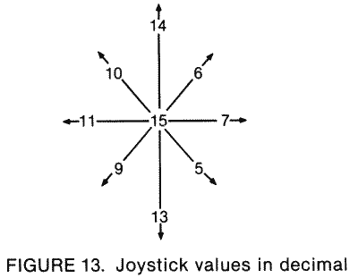
This figure represents the nine possible positions the joystick can be in, along with the value corresponding to each. If you move joystick zero up, for example, STICK0 will have a value of 14. Now, unless you have some brilliant power of observation that I don't, these values don't seem to make any sense. I mean, does "14" mean "up" to you? Not to me. They must make some kind of sense to the computer, however, so let's take a look at them again (Figure 14), this time in binary (the way the computer sees them).
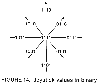
It may not be immediately obvious, but now things make sense. Notice how the first bit (the digit on the right) of each value is only equal to zero when the joystick is up (straight up or diagonally up)? And the second bit is only zero when it's down, the third when it's left, and the fourth when it's right. So we get Figure 15.
And that's why the numbers don't make sense when you first look at them.
| ---0 |
means "up" |
| ---1 |
means "not up" |
| --0- |
means "down" |
| --1- |
means "not down" |
| -0-- |
means "left" |
| -1-- |
means "not left" |
| 0--- | means "right" |
| 1--- | means "not right" |
FIGURE 15. Joystick bit chart
Here are a couple of machine language routines to help you make a little more sense out of the joystick values. One looks for vertical movement and will return a zero for up, one for center, and two for down. The other looks for horizontal movement and returns a zero for left, one for center, and two for right. As you'll see from the following example, these values can prove to be very practical:
100 DIM STICKV$(19):DIM STICKH$(22)
110 FOR CHAR=1 TO 19
120 READ CODE
130 STICKV$(CHAR,CHAR)=CHR$(CODE)
140 NEXT CHAR
150 FOR CHAR=1 TO 22
160 READ CODE
170 STICKH$(CHAR,CHAR)=CHR$(CODE)
180 NEXT CHAR
200 GRAPHICS 0:POKE 752,1
210 PRINT :PRINT "Machine language joystick example"
220 POSITION 10,4:PRINT "VERTICAL VALUE:"
230 POSITION 8,6:PRINT "HORIZONTAL VALUE:"
240 VERT=USR(ADR(STICKV$),0)-1
250 HORZ=USR(ADR(STICKH$),0)-1
260 POSITION 26,4:PRINT VERT;" "
270 POSITION 26,6:PRINT HORZ;" "
280 GOTO 240
290 GOTO 250
1000 DATA 104,104,133,213,104,170,189,120,2,41,3
1010 DATA 201,2,240,1,74,133,212,96
2000 DATA 104,104,133,213,104,170,189,120,2,74,74
2010 DATA 73,2,201,3,208,2,169,2,133,212,96
If you wanted to read joystick one instead of joystick zero, you'd use USR(ADR(STICKV$),1) and USR(ADR(STICKH$),1).
Here's the assembly code that's stored in the DATA statements:
68
STICKV PLA
68 PLA
85D5 STA $D5
68 PLA
AA TAX
BD7802 LDA STICK0,X
2903 AND #$03
C902 CMP #$02
F001 BEQ DONE
4A LSR A
85D4 DONE STA $D4
60 RTS
68 STICKH PLA
68 PLA
85D5 STA $D5
68 PLA
AA TAX
BD7802 LDA STICK0,X
4A LSR A
4A LSR A
4902 EOR #$02
C903 CMP #$03
D002 BNE DONE
A902 LDA #$02
85D4 DONE STA $D4
60 RTS
68 PLA
85D5 STA $D5
68 PLA
AA TAX
BD7802 LDA STICK0,X
2903 AND #$03
C902 CMP #$02
F001 BEQ DONE
4A LSR A
85D4 DONE STA $D4
60 RTS
68 STICKH PLA
68 PLA
85D5 STA $D5
68 PLA
AA TAX
BD7802 LDA STICK0,X
4A LSR A
4A LSR A
4902 EOR #$02
C903 CMP #$03
D002 BNE DONE
A902 LDA #$02
85D4 DONE STA $D4
60 RTS
STICK0 is a shadow register for the last four bits (the leftmost four) of PORTA at location 54016. It is set to a value other than 15 when a light pen in the leftmost controller jack is pressed on the screen.
STICK1
633 0279
Same as STICK0 except it's a shadow register for the first four bits of PORTA rather than the last two. It's also, of course, the value for joystick one rather than joystick zero.
STICK2
634 027A
Same as STICK1 except it's for joystick two, and it's also a shadow register for the last four bits of PORTB (54017).
STICK3
635 027B
Joystick three (the rightmost one) value and a shadow register for the last four bits of PORTB.
PTRIG0
636 027C
If you press the trigger on paddle zero, PTRIG0 will have a value of zero. If you don't press it, PTRIG0 will have a value of one.
PTRIG0 through PTRIG3 get their values from bits two, three, six, and seven of PORTA (54016), respectively. Because these are the same bits that tell whether joysticks one and two are moved to the right or left (see STICK0), you can use the trick in Figure 16.
| PTRIG(1)-PTRIG(0) | = -1 if joystick zero is moved to the left |
| =0 if joystick zero is in the center | |
| =1 if joystick zero is moved to the right |
FIGURE 16. PTRIG chart
The same holds true for PTRIG(3)-PTRIG(2) and joystick one. You can use this trick to make horizontal movement easier to program. Just add the value of the PTRIG difference to your old horizontal position. This saves trying to figure out the joysticks. For the same ease in vertical movement, use the routine given for STICK0.
PTRIG1
637 027D
Same as PTRIG0 but for paddle one.
PTRIG2
638 027E
Trigger value for paddle two.
PTRIG3
639 027F
Trigger value for paddle three.
PTRIG4
640 0280
Trigger value for paddle four.
PTRIG4 through PTRIG7 get their values from bits two, three, six, and seven of PORTB (54017), respectively. The same trick for horizontal movement that was described under PTRIG0 can be applied to joystick two and joystick three using PTRIG4 through PTRIG7.
PTRIG5
641 0281
Trigger value for paddle five.
PTRIG6
642 0282
Trigger value for paddle six.
PTRIG7
643 0283
Guess.
STRIG0
644 0284
Well, here we are again at another new, different, and challenging name for a location. For the next three as well, actually. All three STRIG locations hold the values for the joystick button, and work exactly the same way as PTRIG (zero means pressed).
The STRIGs are shadow registers for the TRIGs (53264 to 53267).
STRIG1
645 0285
STRIG2
646 0286

STRIG3
647 0287
CSTAT
648 0288
CSTAT is the cassette status register.
WMODE
649 0289
This location tells the cassette handler whether the cassette is to be read from (0) or written to (128).
BLIM
650 028A
When the cassette handler reads in a record, the 132 bytes in that record are stored in CASBUF (1021). BLIM tells how many of those bytes are data that we want to give to the user. It is set according to one of the control bytes in the record, and since this probably doesn't make any sense to you, you should go read the description of CASBUF if you want more information.
Noname
651-655 028B-028F
More spare bytes that you shouldn't use because future versions of the OS might use them. Locations 651 and 652 are already used by version "B" as part of the interrupt handler routines.
The display handler uses the next 48 locations. Note that not all locations are used in all graphics modes.
1n the case of a graphics mode with a text window, the display handler takes care of the screen, while the screen editor takes care of the text window. Two separate IOCBs are used for this purpose (see locations 832 to 959), along with two separate cursors.
You should look at SWPFLG (123) for additional information about locations 656 to 667.
TXTROW
656 0290
The row that the text window cursor is currently in. Because there are only four rows in the text window, TXTROW ranges from zero to three.
TXTROW is the text window equivalent of ROWCRS at location 84.
TXTCOL
657,658 0291,0292
The column that the text window cursor is currently in. There are 40 columns in the text window, so TXTCOL can range from 0 to 39. "Ahah," you say. That means location 658 never gets used (since it's only needed when the column number is greater than 255). This is true under normal circumstances, but if you change the text window to be something other than graphics zero, you may need it.
TINDEX
659 0293
While we're on the subject of changing the text window graphics mode, TINDEX tells the OS what graphics mode the text window is (also see DINDEX at location 87). If you decide you'd like a different text window, you'll have to change the display list as TINDEX. Use the program for location SDLSTL (560,561) to look at the display list and see where the text window is. I won't go over it here because for most uses you'll probably just want to mix graphics modes. If that's not the case, however, it's easy to figure out how to make the necessary changes. Just look for the CHR 2 commands at the end of the display list. See location 559 and the appendices for more information.
TXTMSC
660,661 0294,0295
The address of the upper left-hand corner of the text-window screen memory. See SAVMSC (88,89) for the address of regular screen memory.
TXTOLD
662-667 0296-029B
Check out locations 90 through 95, OK? These six locations are the text-window equivalent, so I won't bother explaining them again.
TMPX1
668 029C
This, along with the next three locations, is used for temporary storage. They are used in one or more of the computer's routines as a place to store information during the routine. Once the routine is over, the values in them are no longer meaningful.
TMPX1, in case it wasn't clear, is a temporary location.
HOLD3
669 029D
A temporary location (the location isn't temporary, its use is).
SUBTMP
670 029E
Another temporary location.
HOLD2
671 029F
And yet another temporary location.
DMASK
672 02A0
Way, way back at location SHFAMT (111), we had a little discussion about masking and making changes to individual pixels in the graphics modes. Remember? Well, go back and refresh your memory anyway.
DMASK holds the mask for the pixel that we want to make changes to. Somewhere way up near the end of the OS ROM, there is a list of all the possible masks. The display handler decides which one is needed and loads it into DMASK. Here are all the different values DMASK can have, as well as the graphics modes they are used with (Figure 17).
By way of explanation, the "1's" are used to look at individual bits and the "0's" to ignore them.
Now why, you may ask, do we need more than one mask for most graphics modes? Graphics modes need anywhere from one to eight bits to represent a character or a pixel. Suppose a particular mode, such as mode nine, needs four bits per pixel. That means that each byte holds two different pixels, right (since a byte is eight bits)? So we need two masks to be able to mask out either pixel. This may be a little confusing to you, but don't worry. Unless you're programming in machine language, it's something that is nice to know but that you'll never need.
| 11111111 | for modes zero, one, and two. |
| |
|
| 11110000 | for modes nine, ten, and eleven. |
| 00001111 | |
| |
|
| 11000000 | |
| 00110000 | for modes three, five, and seven. |
| 00001100 | |
| 00000011 | |
| |
|
| 10000000 | |
| 01000000 | |
| 00100000 | |
| 00010000 | for modes four, six, and eight. |
| 00001000 | |
| 00000100 | |
| 00000010 | |
| 00000001 |
FIGURE 17. DMASK bit chart
TMPLBT
673 02A1
More temporary storage space.
ESCFLG
674 02A2
When the ESC key is pressed, ESCFLG is set to 128 and the next key pressed gets an ESC flag attached to it (for example, pressing ESC twice would cause the second ESC to print a special character on the screen). After the next key has been pressed ESCFLG is reset to 0.
ESCFLG is initialized to zero.

TABMAP
675-689 02A3-02B1
TABMAP tells the OS what columns to move the cursor to when the TAB key is pressed.
When the TAB key is pressed, the cursor is moved to the next column, after the one the cursor is on, that has a tabstop. What's a tabstop? It's nothing more than a flag saying, "Hey, TAB, stop here, OK?" TABMAP is where these tabstops, or flags, are kept. Since you can set a tabstop on any one of the 120 columns in a logical line, TABMAP is 15 bytes long. What? How do you get 120 from 15? Well, since the tabstop for each column is either turned on or turned off, we only need one bit for each column. Fifteen bytes times eight bits per byte equals 120. Oh!
How do you set the tabstops? From BASIC, all you have to do is use the TAB-SET (SHIFT-TAB) and TAB-CLR (CTRL-TAB) keys. From within a program, however, you must change TABMAP yourself. To do this, start with 120 zeroes on a piece of paper. These represent the 120 columns, numbered from 0 on the far left to 119 on the far right. Now change the zeroes to ones in the columns where you want your tabstops. So far so good. The next step is to break the 120 digits into groups of eight and convert them to decimal. See the section on bits and bytes for help in doing this. The last step, now that you have 15 decimal numbers, is to POKE these numbers into TABMAP. You now have your own customized TAB settings.
What restores TABMAP to its original values? Pressing SYSTEM RESET or using a GRAPHICS command (OPENing S: or E: as well). What are its original values? A value of one in every byte. That translates to tabstops at 7, 15, 23, 31, . . . , 119.
A few final words. TABMAP works in graphics mode zero and in text windows only. Also, the left edge of the screen will always to be a tabstop, whether you set it to be or not.
LOGMAP
690-693 02B2-02B5
When you're writing or editing your BASIC program, the screen editor needs to know where each logical line begins. Why? Just so that it can make sense out of what's on the screen. Remember, a program listing on the screen may make sense to you, but to the computer it's just a bunch of bytes in memory. With the help of LOGMAP, at least it knows what row on the screen a program line begins on.
LOGMAP works in much the same way as the preceding TABMAP. There are 24 rows in a graphics zero screen, so there are 24 bits in LOGMAP. Actually, there are 32 bits (four bytes), but the last byte doesn't get used. The first byte handles rows 0 through 7, the second handles 8 through 15, and the third handles 16 through 23. If a logical line begins on a certain row, then the corresponding bit is set to one. If the row is part of a previous logical line, then the bit is set to zero.
All the bits in LOGMAP are set to one when the computer is first turned on, SYSTEM RESET is pressed, a GRAPHICS command is used, the text screen is OPENed, or the text screen is cleared. This is because all the lines are blank, and therefore considered to be the start of a logical line.
LOGMAP is updated when you first enter a logical line (with the RETURN key), edit a line, delete a line, or insert a line. Under all these circumstances, the position of the logical lines on the screen will be altered, thus the need for updating.
INVFLG
694 02B6

INVFLG works similiarly to ESCFLG except it keeps track of the inverse video key (the Atari logo key) instead of the ESC key. It is initialized to 0, which means that all the characters you type in will be normal. But when you press the inverse video key, INVFLG gets set to 128 and characters that you type in now will appear in inverse video (black on white instead of white on black). Pressing the inverse video key again will restore INVFLG to 0 and get things back to normal.
Yon should be aware that changing INVFLG will only affect characters that are typed in after you change it. That means that you can't use it like this:
POKE 694,128:PRINT "INVERSE?"
Machine language programmers might be interested to know that INVFLG is always XORed with the character value, regardless of INVFLG's value (this should tell you that the value for an inverse video character is just that for a regular character with bit seven set, i.e., the regular value plus 128). This means that you can have fun with the keyboard by POKEing INVFLG with something other than 0 or 128. Try it, it's fun !
FILFLG
695 02B7
If FILFLG is not equal to zero, then we're in the middle of a FILL.
TMPROW
696 02B8
A temporary storage place for the value in ROWCRS (84).
TMPCOL
697,698 02B9,02BA
More temporary storage, this one for the value in COLCRS (85,86).
SCRFLG
699 02BB
This one is somewhat complicated. First of all, it keeps track of how many physical lines (as compared to logical lines) have been scrolled off the top of the screen. If you keep pressing RETURN, it will eventually count up to 255 and then wrap back around to 0. No problem so far. According to the OS listing, however, it is also used during the character insertion process (when you press SHIFT-INSERT). Apparently, if you insert a character, SCRFLG gets set to 0. If the insertion caused the screen to scroll up, then the number of lines it scrolled (which depends on how long the logical line at the top of the screen was, so it could be from one to three) is stored in SCRFLG. The value in SCRFLG is then used to reposition the cursor, leaving SCRFLG with a final value of 255.
HOLD4
700 02BC
HOLD4 is used to temporarily hold the value of ATACHR (763) during the FILL routine.
HOLD5
701 02BD
Same as the above register (HOLD4).
SHFLOK
702 02BE
When SHFLOK is set to 0, all text typed in will be in lower case. Set it to 64, and all text will be in upper case. Finally, 128 will give you all control and graphics characters.
The following key combinations affect SHFLOK:
CAPS/LOWR sets it to 0.
SHIFT-CAPS/LOWR sets it to 64.
CTRL-CAPS/LOWR sets it to 128.
In addition, POKE in 192 and only numbers and punctuation will be recognized if pressed. Finally 255 in this location will not allow any letters at all to be recognized. Remember that these two POKES work on input from the keyborad only. You can still write letters to the screen or printer. This means their practical use is to prevent inputs you don't want.
Note that SHFLOK does not indicate whether or not the SHIFT or CTRL keys are pressed.
SHFLOK is initialized to 64.
BOTSCR
703 02BF
BOTSCR tells how many lines of text are available for use by the screen editor. What does this mean? Well, it can use all 24 lines in graphics mode zero, so BOTSCR would have a value of 24. In a mode with a text window, there are four lines in the text window that it can use, so BOTSCR would have a value of four. In all other modes there are none, so BOTSCR has a value of zero. What about graphics modes one and two? you say. In these modes the screen editor takes care of the text window, while the display handler takes care of the rest (at least in terms of PRINTing text, which is what we're really talking about here).
Try the following program:
100 GRAPHICS 0
110 POKE 703,4
120 FOR ROW=0 TO 19
130 POSITION 2,ROW
140 PRINT #6;"We have to print #6 up here"
150 NEXT ROW
160 PRINT "But now we have a text window here!"
170 PRINT
180 GOTO 160
110 POKE 703,4
120 FOR ROW=0 TO 19
130 POSITION 2,ROW
140 PRINT #6;"We have to print #6 up here"
150 NEXT ROW
160 PRINT "But now we have a text window here!"
170 PRINT
180 GOTO 160
COLOR
The next nine locations, 704 through 712, are called "color registers." This is just a fancy way of saying that they tell ANTIC what colors to put on the screen. How do you convert a color into a number that you can store here? The Atari has a total of 16 colors that you can choose from, and each is assigned a number. The exact colors vary slightly from television set to television set, so it's difficult to describe them exactly. Bear that in mind when you consult the chart in Figure 18.
| COLOR | VALUE | COLOR | VALUE |
| Black | 0 |
Blue | 8 |
| Rust
|
1 |
Deep blue | 9 |
| Reddish orange | 2 |
Dull blue | 10 |
| Dark orange | 3 |
Olive
green |
11 |
| Red | 4 |
Green | 12 |
| Purplish blue | 5 |
Dark green | 13 |
| Cobalt blue | 6 |
Orangey green | 14 |
| Ultramarine | 7 |
Orange | 15 |
FIGURE 18. Color value chart
OK, now somewhere in the back of your mind you're probably thinking "Wait a minute, aren't there supposed to be 256 possible colors on the Atari?" Yes and no. There are only 16 colors, but there are also 16 shades of each color, resulting in a total of 256 (16 times 16) possible "colors." That's not even true either. Even though you can specify a brightness value from 0 to 15, 0 and 1 will be the same brightness, as will 2 and 3 and so forth. That gives us a true total of 128. 128 combinations of color and brightness, however, will be more than you need, or can use at one time.

So now we have a color value and a brightness value. Since each color register is only one byte, we're obviously going to have to somehow combine these two values together. If you're familiar with hexadecimal, you will probably know how already. Recall that in hexadecimal, each byte has two digits, each of which can have a value from 0 to F (15). All we do to combine our color and brightness is to have the first digit be the color, and the second the brightness. If you're using decimal, you want to multiply the color value by 16 and add the brightness. That's how you figure out the value to POKE into the appropriate color register (you can also use the SETCOLOR command for the playfield registers).
PCOLR0
704 02C0
This is the color register for player zero and missile zero. It is also used to hold the background color in GTIA mode 10.
The SETCOLOR command will not work on this or any of the next three locations.
PCOLR0 is a shadow register for COLPM0 at location 53266.
PCOLR1
705 02C1
The color register for player one and missile one. It is a shadow register for COLPM1 at location 53267.
PCOLR2
706 02C2
The color register for player two and missile two. It is a shadow register for COLPM2 at location 53268.
PCOLR3
707 02C3
The last player/missile color register, this time for player three and missile three. It is a shadow register for COLPM3 at location 53269.
COLOR0
708 02C4
Lots of information for this guy. This is the color of playfield zero. It is also called color register zero, is a shadow register for COLPF0 at location 53270, specifies the color of uppercase letters in graphics modes one and two, and can be set by the BASIC SETCOLOR command (as can the next four locations). Whew!
COLOR1
709 02C5
This hold the color value for playfield one, is called color register one, is a shadow register for COLPF1 at location 53271, and specifies the color of lowercase letters in graphics modes one and two.
COLOR1 is also used to specify the brightness of the characters in graphics mode zero, and of the pixels in graphics mode eight. As you know, you can only draw with one color in graphics mode eight, right? Well, not quite. Through a process called "artifacting," you can get up to four.
Briefly, because the pixels are so small in graphics mode eight, a pixel in an odd-numbered column will have a different color than one in an even-numbered column. Don't ask why, just try the following program:
100
GRAPHICS 8
110 COLOR 1
120 FOR COL=10 TO 20 STEP 2
130 PLOT COL,10
140 DRAWTO COL,20
150 NEXT COL
160 FOR COL=31 TO 41 STEP 2
170 PLOT COL,10
180 DRAWTO COL,20
190 NEXT COL
110 COLOR 1
120 FOR COL=10 TO 20 STEP 2
130 PLOT COL,10
140 DRAWTO COL,20
150 NEXT COL
160 FOR COL=31 TO 41 STEP 2
170 PLOT COL,10
180 DRAWTO COL,20
190 NEXT COL
Viola! Two new colors. But how do we get the regular white, and where does the fourth color come from? You know, you ask a lot of questions. If we plot an even-numbered column and then the following odd-numbered column, we get white. If, on the other hand, we plot an odd-numbered column and then the following even-numbered one, we get the fourth color. Make sure you understand the difference between the two. Add the following lines to the preceding program:
200
FOR COL=50 TO 60 STEP 4
210 PLOT COL,10:DRAWTO COL,20
220 PLOT COL+1,10:DRAWTO COL+1,20
230 NEXT COL
240 FOR COL=71 TO 91 STEP 4
250 PLOT COL,10:DRAWTO COL,20
260 PLOT COL+1,10:DRAWTO COL+1,20
270 NEXT COL
210 PLOT COL,10:DRAWTO COL,20
220 PLOT COL+1,10:DRAWTO COL+1,20
230 NEXT COL
240 FOR COL=71 TO 91 STEP 4
250 PLOT COL,10:DRAWTO COL,20
260 PLOT COL+1,10:DRAWTO COL+1,20
270 NEXT COL
Doing things this way kind of restricts you in the way you plot and draw, but it does give you more colors. You should also note that the CTIA and GTIA chips switch the odd and even colors on the screen. This usually makes red on one computer look like green on another. Also, the colors you do get will depend on the values in COLOR1 and COLOR2 (following).
COLOR2
710 02C6
This holds the color value for playfield two, is called color register two, is a shadow register for COLPF2 at location 53272, and specifies the color of inverse uppercase letters in graphics modes one and two.
In graphics modes zero and eight, COLOR2 specifies the background color.
COLOR3
711 02C7
OK, you should be getting the hang of this by now. This is the same as COLOR2, but with threes instead of twos. It's also the color of inverse lowercase letters in graphics modes one and two.
COLOR4
712 02C8
Same as the preceding but for the background color. It is a shadow register for COLBK at location 53274. Don't forget that in GTIA modes, PCOLR0 (704) is the background color, while COLOR4 is just a regular color register.
Noname
713-735 02C9-02DF
These 23 are currently unused.
The following four bytes, from 736 to 739, are used by DOS. That means that they are unused if you are not using DOS.
RUNAD
736,737 02E0,02E1
When you load a binary load file from DOS, sometimes it will run automatically and sometimes it won't. What makes the difference? If the binary load file stores an address in RUNAD, then DOS will go (JSR) to that address after the file has been loaded. Otherwise, the DOS menu will stay on the screen. See your DOS manual for more information under the sections on binary loading and saving.
INITAD
738,739 02E2,02E3
Whoops! I lied slightly in the last location. If a binary load file alters INITAD, then DOS immediately goes (JSR again) to the address in INITAD before continuing to load the file. You can use this to do stuff like put a message or picture on the screen while the rest of the file is loading. Make sure that the routine whose address you're putting in INITAD ends with an RTS. Also, if you want DOS to return to the menu after executing the RUNAD routine, make sure it ends with an RTS instruction.
So where was the lie? If you don't end the INITAD routine with an RTS instruction, the RUNAD routine will never be executed (and you may run into problems with future disk I/O).
RAMSIZ
740 02E4
RAMSIZ has a similar function to RAMTOP (106), so go back and read up on RAMTOP. The main difference is that RAMSIZ doesn't cause the screen memory to move when you change it and do a graphics call. Experiment to see how it works.
MEMTOP
741,742 02E5,02E6
MEMTOP holds the address of the last free memory location. This does not mean the top of RAM. Why not? You're forgetting that the screen memory and display list are put at the end of RAM. MEMTOP is the last location that is unused, and is therefore the location right below the display list. Originally, however, before any graphics mode is set up, it does hold the same address as RAMSIZ.
Anything that results in the display handler changing the screen memory and display list also results in MEMTOP getting changed. That means SYSTEM RESET, the GRAPHICS command, and OPENing the screen.
For more information on MEMTOP's use (yes, I'm going to send you somewhere else again), see APPMHI at locations 14 and 15.
MEMTOP is called HIMEM by BASIC, since BASIC has its own MEMTOP at locations 144 and 145.
MEMLO
743,744 02E7,02E8
Since we have a pointer to the top of free memory, it only makes sense to have one to the bottom of free memory. MEMLO holds the address of the first byte in RAM that is available for your use. Notice that BASIC uses a different pointer for the first free byte, called LOMEM (128,129). Although some sources imply otherwise, MEMLO and LOMEM seem to always contain the same value, which is not touched by the OS after the powerup routine is done.
The first free location in memory is usually at 1792. If you're using DOS, however, DOS needs some extra space for something called the "FMS buffers" (see SABYTE [1801], DRVBYT [1802], and the glossary). This means that MEMLO will be greater when DOS is present (by 128 for each buffer).

Let's talk about reserving memory for your own private use. We last discussed this at RAMTOP (106), where we saw how to reserve memory above screen memory. But, alas, this technique wasted up to 800 bytes because of a problem with scrolling the screen. So now we come to the alternative of reserving memory at the other end of RAM, below everything else. How do we do it? There are two possibilities. First of all, you could write an AUTORUN.SYS file that loads MEMLO with the values you want. De Re Atari has an excellent example of how to do this, but it's obviously a technique that requires a knowledge of machine language. What if you're working in BASIC? Well, there's a problem. Remember that BASIC also keeps a pointer to the bottom of free memory. It's called LOMEM and I have mentioned it. If we change MEMLO, we also have to change LOMEM. We can do this by POKEing both MEMLO and LOMEM, but that confuses BASIC because it loses some important information that it had already stored in the memory area you just told it not to look at. That's a problem. What happens if you POKE MEMLO and then type NEW (NEW transfers the value of MEMLO into LOMEM and resets all the program pointers)? Nothing bad; in fact it does exactly what we wanted. But we still have a problem: this method only works when you make the changes yourself; it won't work from inside a program. As it turns out, and it makes sense if you think about it, there is nothing you can do from within a BASIC program to reserve memory using MEMLO (without destroying the program). This means that the MEMLO method of reserving memory is only useful if you're programming in machine language (or if you first boot up an AUTORUN.SYS file as described). Sorry folks.
SYSTEM RESET will restore MEMLO to its original value. The program in De Re Atari, as mentioned, uses the SYSTEM RESET vector to make sure that MEMLO does not get reset.
Only NEW (or turning off the computer) will restore LOMEM.
Noname
745 02E9
Currently unused. This is, however, subject to change in future versions of the OS.
DVSTAT
746-749 02EA-02ED
This one is for experts only, so don't expect it to sound pretty. When you send a GET STATUS command (83) to a device, these bytes are set according to the type of device and its status. They seem to be set only by the printer handler, the disk handler (not the disk file manager), and the RS-232 handler.
Location 746 gives the command status. Because it is interpreted differently for each device, you should consult either the OS manual or the 850 Interface manual for details (this isn't a cop-out on my part; the information in this byte is useful only to extremely competent machine language programmers).
If the GET STATUS were to a printer, location 747 contains the AUX2 byte of the previous operation. If it were to a disk drive, location 747 holds the value of the status byte of the disk controller chip (if you really need to know more details, find some documentation on the INS1771-1 Floppy Disk Controller chip). Finally, if it were to the 850 Interface, location 747 could indicate one of two things. If concurrent mode I/O is not active, then it will hold information regarding the monitored readiness lines (DSR, CTS, and CRX) and the data receive line (RCV) of the specified port. Please see your 850 Interface manual for more details.
If concurrent mode I/O were active, location 747, in conjunction with location 748, will hold the number of characters currently in the input buffer.
For the printer and disk drive, a GET STATUS command will return the maximum timeout value for the device. This value is provided by the device controller and is initialized to 31. A value of 64 here represents one second.
Location 749 is only used for the 850 Interface, and only if concurrent mode I/O were active at the time of the GET STATUS. In that case, it holds the number of characters currently in the output buffer.

If you got this far and you're confused, don't worry. By the time you have a need to use DVSTAT, it should be easier to understand. I've been programming the Atari for five years and have only recently found a need for it.
CBAUDL, CBAUDH
750,751 02EE,02EF
The speed at which programs load in from cassette is called the "baud rate," and this is what is stored in CBAUDL/H. It's initialized to 1484 by the OS, which represents 600 baud ("baud," by the way, stands for "bits per second"; don't ask how they got one from the other). Unfortunately, sometimes the data on the cassette tape is stored a little slower or faster than 600 baud. This may be due to the speed of the cassette motor, the tape being stretched slightly, or other such minor details. In any case, at the beginning of each cassette record (remember that a record is just a bunch of bytes) are two bytes that have alternating zeroes and ones (01010101; 85). These bytes are used to set the baud rate exactly, so speed variations can be compensated for.
AUDF3 (53764) and AUDF4 (53766) are used to store the baud rate and do the actual timing.
CRSINH
752 02F0
This one should come as a reward to you for trudging through the sludge of the last few locations. CRSINH is used to make the cursor invisible (and visible again). This comes in handy when you've got a message or something on the screen and you don't want whoever's reading it to see the cursor. All you have to do is POKE CRSINH with something other than a zero. To make the cursor visible again, just POKE it with a zero. That's (almost) all there is to it.
Hold it, what was the "almost" that was trying to hide in the parentheses back there? Well, there is one tiny thing I forgot to mention. The cursor won't disappear (or reappear) until you move it for the first time after you change CRSINH. All that means is you have to have a PRINT of some kind after the POKE. The easiest way around this is just to POKE CRSINH before you print anything on the screen. For example,
100 POKE 752,1
110 PRINT
110 PRINT
CRSINH is set to zero when you turn on the computer, and also when you press BREAK, press SYSTEM RESET, use a GRAPHICS command, or OPEN either "S:" or "E:".
Also see CHACT at location 755 for another way to tell the cursor to get lost.
Here is a way to place dots all over your screen so that you can check the convergence of the TV or monitor:
10 POKE 710,0:POKE 752,1:POKE 82,0
:FOR I=1 TO 959:? ".";:NEXT I
20 GOTO 20
20 GOTO 20
KEYDEL
753 02F1
A lot of you have probably heard the term "debounce" (no, it's not from a commercial for French shampoo). Some of you probably don't have the slightest idea what it means, so let's talk debounce for a bit.
When you press a key, you're actually bringing two little bits of metal together. When the two touch, electricity flows through them and tells the computer that the key is pressed. Sometimes, when the two first hit each other, they bounce a little. This has the effect that they are touching, then they're not touching, and then they're touching again, which the computer would normally interpret as meaning the key was pressed twice. You only pressed it once, however, so somehow the computer has to be smart enough to realize this. The process it uses is called "debouncing" and it's fairly simple. If a bounce occurs, it happens real fast, too fast for you to have been able to hit the key twice. So, the OS waits a little while after you first press the key before looking to see if you pressed it again. That way, it doesn't see the bounce. KEYDEL tells it how long to wait.

KEYDEL is set to three whenever a key is pressed and then every stage two VBLANK it's decremented by one. Until it reaches zero, the OS will not let the same key be pressed again. Unless you can press a key faster than 20 times a second, this won't be a problem for you.
CH1
754 02F2
CH1 is the value of the last key pressed (not the current one). When you press a key, the OS checks its value (stored in CH [764]) against CH1. If they're the same, then KEYDEL is checked to make sure that the key has been debounced. If KEYDEL is equal to zero, or if the two values aren't the same, then the current key code is stored in CH1 and the OS goes on to process that key.
CHACT
755 02F3
CHACT does some neat things to the characters on the screen. The bits are used as summarized in Figure 19.
| -------0 | inverse character letters are visible |
| -------1 | inverse character letters are invisible |
| ------0- | inverse character backgrounds are invisible |
| ------1- | inverse character backgrounds are visible |
| -----0-- | all characters are right-side up |
| -----1-- | all characters are upside down |
FIGURE 19. CHACT bit chart
What does this mean? Try typing some inverse characters on the screen (use the Atari logo key). Now POKE 755,1. What happened? That's right, the letters disappear. Try POKE 755,2. This makes the background (the solid white part) disappear. Finally, try POKE 755,3 to make everything disappear (everything in the inverse characters, that is). That should give you a good idea of what the first two bits can do. By the way, since the cursor is essentially an inverse character, it will disappear as well when you make the inverse character background disappear.
The last bit is pretty self-explanatory. Just try POKE 755,4 and see what happens.
What can you use CHACT for? Reverse characters add emphasis to text, CHACT lets you add even more emphasis by making inverse characters blink. Try the following:
100 GRAPHICS 0
105 POKE 752, 1
110 PRINT :PRINT "Add
 to your programs"
120 FOR BLINK=1 TO 10
130 POKE 755,0
140 FOR DELAY=1 TO 50
150 NEXT DELAY
160 POKE 755,2
170 FOR DELAY=1 TO 50
180 NEXT DELAY
190 NEXT BLINK
195 POKE 752,0
Try substituting other values for the zero in line 130. Also see location VVBLKD at 548 and 549 for a machine language routine that uses CHACT to make inverse text blink while you're typing it.
In case you hadn't figured it out already, CHACT is initialized to two.

CHBAS
756 02F4
This is a biggie (have I ever lied?). CHBAS holds the address, in pages (so you multiply the number here by 256 to get the actual address), of the character set. What is a character set? A character set is a whole bunch of numbers that tell the computer how to draw the various characters on the screen. In other words, it tells the computer what the characters look like. How can numbers describe what a character looks like? First of all, you should go read the section near the beginning of the book on bits and bytes. Then come back here.
Back already? OK, what do bits and bytes have to do with character descriptions (why am I asking so many questions)? Well, a byte can be thought of as part of a picture. You know - with the bits being dots in the picture. You turn a bit on, and the corresponding dot in the picture gets turned on. You've already seen how this is used in the graphics modes. Well, the text modes also need to turn dots on and off, but they need to change a whole bunch at once for each character. So what the Atari does is store eight bytes for each character in this special thing called the character set. Each of these descriptions is given a number, and to set the right dots for a particular character, the computer just has to say, "Hey, get me the description for character number whatever and put it on the screen," and the character will magically appear on the screen.
Let's take a look at how those eight bytes make up a character (Figure 20).
| # IN | BIT |
| MEMORY | PATTERN |
| |
|
| 0 |
00000000 |
| 12 |
00001100 |
| 28 |
00011100 |
| 60 |
00111100 |
| 108 |
01101100 |
| 126 |
01111110 |
| 12 |
00001100 |
| 0 |
00000000 |
FIGURE 20. CHBAS bit chart
Now you can see how simple creating characters is. First draw the shape of an 8 x 8 pattern of 0's and 1's. Next add up the value of the ON, or 1, bits. Then POKE these numbers in the proper order into memory. Let's go over the details.
Look at those bits again in terms of dots, with the zeroes meaning no dot, and the ones meaning dot (Figure 21).
##
###
####
## ##
######
##
FIGURE 21. The number 4
###
####
## ##
######
##
FIGURE 21. The number 4
Ahah! The description we used was for the "4" character. You should now be able to see how the descriptions work.
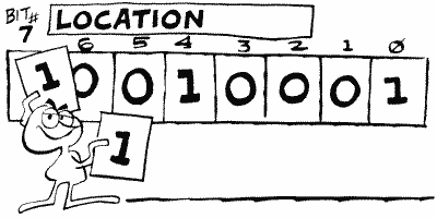
How are the descriptions ordered within the character set? It's not the same order as ATASCII (the order that CHR$ and ASC use). To convert from ATASCII values, which you can find in your BASIC manual, to the character set order, use Table 2.
TABLE 2
| TYPE OF CHARACTER uppercase, numbers, punctuation |
ATASCII NO. 32-95 |
CHAR.
SET NO. 0-63 |
| graphics, characters |
0-31 |
64-95 |
| lowercase |
96-127 |
96-127 |
Now, to find the character description of a particular character, find the ATASCII value (either with ASC or by looking it up in the chart in the BASIC manual), use the preceding chart to convert it to the character set value (more commonly called the "internal" value), multiply that by eight (because there are eight bytes for each character), and add it to PEEK(CHBAS)*256. The result is the address of the first byte of the character description you want.
The character set that comes with the Atari is stored starting at location 57344. You can double-check this by PEEKing CHBAS and seeing that it has a value of 224. There are a total of 128 possible characters (not counting inverse ones), so the character set takes up 128*8 equals 1024 bytes.
In graphics modes one and two, you probably know that you can't have upper- and lowercase letters on the screen at the same time. Why not? In these modes the characters can be one of four possible colors. In order to be able to pull this off, two of the bits in the character number have to be used to specify the color. This means that only six bits are left to specify the character. Six bits are enough to give you the numbers 0 through 63. Zero through 63, if you consult the preceding character order chart, are the uppercase characters, numbers, and punctuation. So what if you want lowercase? The BASIC manual tells you to POKE 755 (CHBAS) with 226 instead of 224. What does this do? It moves the start of the character set forward by 512 (2*256) bytes. Now I know that right now you're thinking to yourself, "Gee, 0 through 63 is a total of 64 characters, and 8 bytes for each character gives me, let me see, uh, 512 bytes!" Hey, you're terrific! What you just caught on to is that changing CHBAS like that simply lets you skip over to the lowercase and graphics characters, the other half of the character set.
Unfortunately, this means that the heart character gets used as a space, so your screen is filled with hearts-romantic, but not what you want. You can get rid of them with SETCOLOR 0,0,0 or by redefining the heart character to a space. See Appendix One for information on how to do the latter.
In graphics mode zero, there's not much more to tell. If an inverse video character is requested (see INVFLG [694]), then the eight bytes for that character are reversed (ones changed to zeroes and vice versa) before they are put on the screen.
CHBAS is a shadow register for CHBASE at location 54281. For some reason you cannot set CHBAS to an odd number, or garbage will fill the screen. Finally, CHBAS can be set to point to your own character set.
"Hold on there, just a second, wait a minute, timeout, take five, whoa! You mean I can design my own character set? And you took all this time before you told me, and now you're going to move on without telling me how to do it? What kind of author are you?"
By the way, please see Appendix One for a complete example of designing your own character set.
Noname
757-761 02F5-02F9
More spare bytes. You know, I have to assume that you're going to come to these locations and forget all about that warning I gave you way back when. You remember, "Don't use spare bytes, they may be used in future versions of the OS." But if you did remember and are getting sick of me telling you every time we come across some spare bytes, then what can I say? It's a rough world out there.
CHAR
762 02FA
This is the internal number (value) of the character that was read or written last by the display handler. A lot of the time the handler will move the cursor as the last step of an operation, so PEEKing here will often return a value of 128 or 0 (for a visible or invisible cursor respectively).
ATACHR gives the ATASCII value corresponding to the internal value in CHAR.
ATACHR
763 02FB
ATACHR is used by the display handler, the screen editor, and the keyboard handler to hold the ATASCII value of the character last read or written. If we're using a graphics mode rather than a text mode, then it's the value of the graphics byte rather than that of the character (for the display handler only). It's also used in converting ATASCII to internal and vice versa, and FILL uses it to hold the color of the area being filled (in which case it gets its value from FILDAT [765]).
CH
764 02FC
CH is the middle guy between the keyboard and the keyboard handler. When a key is pressed, a keyboard value (yes, yet another kind of character value) gets put into CH. The keyboard handler then picks it up, puts it into CH1 (754), and puts a 255 into CH to indicate that it got the value OK. There are a few exceptions to this. First of all, if we're in the middle of debouncing (see KEYDEL [753]). the key is ignored completely; it doesn't even make it to CH. If CTRL-1 is pressed, then SSFLAG (767) is updated, but CH is not affected. Finally, CH also gets changed by the key repeat process mentioned under SRTIMR at location 555. To repeat a key, the OS takes the value in KBCODE (53769) and stores it in CH.
If you are GETting information from the keyboard, make sure you set CH to 255 before you do your GET. This will make sure that any previous key presses are ignored. For example,
100 OPEN #1,4,0,"K:"
110 POKE 764,255
120 GET #1,A
130 PRINT "You pressed key number ";PEEK(754)
140 GOTO 110
110 POKE 764,255
120 GET #1,A
130 PRINT "You pressed key number ";PEEK(754)
140 GOTO 110
You can use this program to find out the values for the various keys, or you can look at the chart on page 50 of the OS manual. In either case, you should notice that the CTRL key adds 128 to a key value, and the SHIFT key adds 64.
Here is my favorite trick for this location. Say you want your program to load in a tape program and then RUN it. It would seem that there is no way to do that because someone has to press the RETURN key after the program loads and you type RUN. NOT TRUE. Use location 764 to hold the RETURN key like this:
10 REM
YOUR PROGRAM HERE
.
.
.
.
2000 POKE 764,12:CLOAD:RUN
.
.
.
.
2000 POKE 764,12:CLOAD:RUN
FILDAT
765 02FD
Simply put, FILDAT is the data to FILL with in the XIO 18 command.
DSPFLG
766 02FE
When DSPFLG is set to a nonzero value, then CTRL characters like CTRL-CLEAR, CTRL-DELETE, CTRL-arrow, and so forth will appear as a character on the screen rather than having some kind of effect on the screen (such as clearing it or moving the cursor). If it's equal to zero, then they have their normal effect.
Note that to type a CTRL character so that it appears on the screen, you press ESC before you type that character. ESCFLG (674) is ORed with DSPFLG before the character is processed. That means that the ESC key is not the only way to get CTRL characters to appear. That's good. Suppose, for example, that you want to print the arrow characters on the screen from BASIC. You can use the ESC key to type them into a string, but when you try to print that string to the screen, BASIC will move the cursor rather than print the arrows. What you have to do is POKE 766,1 before you try and print the string. Be sure to change it back afterwards.
SSFLAG
767 02FF
SSFLAG is used to pause a program or a LISTing. When it's set to 0, everything works as usual. When set to 255, however, the pause is in effect and will stay that way until it's set back to 0 again. If the basic idea of this sounds like something you've run across before, that's because it is. The CTRL-1 key, which you have probably used to pause your LISTings, changes SSFLAG. You can also change SSFLAG yourself, but if you do it from within a BASIC program, keep in mind that the program is paused, so you won't be able to change it back unless somebody presses CTRL-1! Try this:
100
POKE 202,1
110 PRINT "Now try LISTing this program"
110 PRINT "Now try LISTing this program"
SSFLAG has no effect on machine language routines, which is why you can't use CTRL-1 to pause some programs.
PAGE
THREE
You probably aren't going to be too thrilled with page three. Why? It's all about I/O. That means that you may not understand a lot of it, because I/O can get real complicated real fast. Don't worry too much about it, though. BASIC has commands that take care of these locations for you, so you're only reading about these locations for enlightenment. If, on the other hand, you're programming in machine language...
Before you go any further, make sure you've read and at least vaguely understood the appendix on I/O. It's not that long, or complicated, but it will give you a nice overview of what everything here is used for.
The first part of page three, locations 768 through 831, is used for the "device handlers." As the name implies, device handlers are used to handle I/O to the various devices. What devices can we have? The screen (S:), the screen editor (E:), the keyboard (K:), the cassette player (C:), the disk drive (D:), the printer (P:), and the RS-232 ports on the 850 interface (R:); all of these handlers, which are just machine language routines, are a part of the OS, with the exception of the RS-232 handler. The RS-232 handler is stored inside the 850 interface, and gets transferred over to the Atari when you turn on the system.
Locations 768 through 779 make up the Device Control Block (DCB; see the appendix on I/O for an explanation). To use the DCB you must set it with the appropriate values and then JSR DSKINV (58451) for disk I/O, or JSR SIOV (58457) for other device I/O.
DDEVIC
768 0300
Three of the devices, S:, E:, and K:, are a part of the computer. The others are all outside the computer, and we therefore need to have some way of talking to them. The "serial bus" takes care of that (the cords you use to connect the devices together are the visible part of the serial bus). But, since you can have more than one device hooked up to the serial bus, you need some way of telling the bus which device you want to talk to. Each device is therefore assigned a number (think of it as a phone number), and the handler gives DDEVIC the number of the device it wants to talk to. Do not change DDEVIC yourself.
Here are the numbers for the various devices (Figure 22).
| Disk Drive | 49
($31) |
| Printer
1 |
64
($40) |
| Printer
2 |
79
($4F) |
| RS-232
Port |
80
($50) |
| Cassette |
96
($60) |
FIGURE 22. DDEVIC chart
DUNIT
769 0301
We can have up to four disk drives and RS-232 ports. DUNIT holds the number of the disk drive, printer, or RS-232 port we want.
DUNIT gets added to DDEVIC, and the result stored in CDEVIC at location 570. CDEVIC is then used during the actual I/O.
DCONIND
770 0302
Once it has got the number of the device we want to talk to, the handler has to know what it should tell the device to do. For that we have another bunch of numbers, this time for the various commands (Figure 23).
| Get Sector | 82 ($52) |
| Put Sector (with verify) | 87 ($57) |
| Put Sector (w/o verify) | 80 ($50) |
| Get Status | 83 ($53) |
| Format Disk | 33 ($21) |
| Download | 32 ($20) |
| Read Address | 84 ($54) |
| Read Spin | 81 ($51) |
| Motor On | 85 ($55) |
| Verify Sector | 86 ($56) |
FIGURE 23. DCOMND chart
This is one of those tables that gives you the confidence that you know what's going on, until you get about halfway down. The first five commands are probably the only ones you'll ever run into, so don't worry too much about it.
DDEVIC gets transferred over to CDEVIC (570) for use by SIO.
DSTATS
771 0303
Two uses for DSTATS. First of all, after an I/O operation is complete, it holds the status of the operation. A zero means that everything went OK. See the OS manual for the meaning of nonzero values.
Before the I/O operation, DSTATS tells SIO how data is going to be transferred, using bits six and seven as in Figure 24.
| 00------ ($00) means no data will be transferred in this operation. |
| 01------ ($40) means data is going to be read from the device. |
| 10------ ($80) means data is going to be written to the device. |
| 11------ ($00) is not a valid combination. |
FIGURE 24. DSTATS chart
DBUFLO,DBUFHI
772,773 0304,0305
This is a pointer to the buffer that will be used to store the data that is to be sent or received during I/O. It's set by the handler to the system buffer at CASBUF (1021) unless you tell the handler differently.
If a GET STATUS command is given, then DBUFLO/HI is set to point to DVSTAT (746).
If you're communicating with SIO directly, you should make sure you set DBUFLO/HI yourself.
DTIMLO
774 0306
DTIMLO is the timeout value for the device being used and is set by the handler. You will recall from our other run-ins with timeouts that a value of 60 here represents 64 seconds.
DTIMLO is initialized to 31.
DUNUSE
775 0307
Another unused byte (warning, warning!).
DBYTLO, DBYTHI
776,777 0308,0309
This location specifies the number of data bytes that are to be read to, or written from, the buffer during I/O. It is also used by the FORMAT command to store the number of bad sectors.

The values in DBUFLO/HI and DBYTLO/HI are added together after the I/O is over, and the results stored in BFENLO/HI (52,53).
Just in case you thought the OS was perfect, there's a bug that messes things up if the last byte in the buffer is in an address that ends in $FF (such as $41FF, $32FF, etc). Be careful about this.
DAUX 1, DAUX2
778,779 030A,030B
These are used to provide information that is unique to the specific device (a sector number, for example). Their values are transferred to CAUX1 and CAUX2 at locations 572 and 573.
The next 14 locations (780 to 793) have various SIO uses.
TIMER1
780,781 030C,030D
TIMER1 is the initial timer value for the baud rate. What does that mean? Back at CBAUDL/H (750,751) we discovered what a baud rate is and how the OS constantly adjusts it during I/O. We found out that an alternating bit pattern is read and timed in order to figure out the correct rate. TIMER1 stores the time at the beginning of this pattern, and TIMER2 below stores the time at the end of it. The difference in these times is then used to figure out the new baud rate.
The first byte of both TIMER1 and TIMER2 is the value of VCOUNT (54283) at the time, and the second is the value of RTCLOK+2 (20).
ADDCOR
782 030E
ADDCOR is an "addition correction flag" used in the baud rate calculations. Those quotation marks mean that you'll never need to know what it means.
CASFLG
783 030F
Part of the SIO routine is not needed for cassette I/O, so CASFLG is used to warn SIO that cassette I/O is being done. A value of 0 means regular SIO, 255 means cassette.
TIMER2
784,785 0310,0311
This is the final timer value for baud rate. See TIMER1 for a complete description.
TEMP1
786,787 0312,0313
TEMP1 is used as a temporary storage location for the difference in the TIMER1/2 values during the baud rate calculation.
TEMP2
788 0314
Supposedly another temporary storage location of some sort, but according to the OS listing it isn't used.
TEMP3
789 0315
Another temporary storage location that is used, but for nothing particularly important.
SAVIO
790 0316
Back to setting the baud rate. Remember the alternating bit pattern (see TIMER1 if not)? SAVIO is used to check the serial port SKSTAT (53775) to see if the next bit has come in yet. That's all.
TIMFLG
791 0317
This is a flag to indicate that the cassette player has timed out (taken a snooze). If it's equal to one, we're OK. If it's equal to zero, then we're in timeout territory.
For the cassette player to timeout, a data byte must not be found within the given time period (which can vary). This usually indicates that the baud rate was wrong, assuming that you remembered to connect the cassette player, plug it in, put in the program tape, and press "PLAY"!
STACKP
792 0318
Remember the stack at page one? When SIO first gets going, it stores the value of the stack pointer in STACKP. That way, if somebody presses BREAK before it's done, it can restore the stack pointer and return to where it was called from.
TSTAT
793 0319
This is used to temporarily hold the value of STATUS (48) during I/O.
HATABS
794-831 031A-033F
We now know a little about what handlers do, but where do we find them? Obviously HATABS is going to have something to do with it, but before I tell you what, let's talk a little more about handlers.
Each handler is made up of a bunch of routines that perform different I/O functions. These functions are shown in Figure 25.
| OPEN device |
| CLOSE device |
| GET BYTE from device |
| PUT BYTE to device |
| GET STATUS of device |
| SPECIAL |
| INITIALIZE device |
FIGURE 25. I/O functions chart
Since SIO is going to need to know where each of these routines is, it's useful to keep the address of each routine in a table. We'll only need the initialization routine once, so we'll put a JMP instruction in the table right before the initialization address. Finally, we'll call this table the "handler entry point" table, which makes sense if you think about it.
OK, so now we have a handler entry point table for each of our handlers. Now we need a table of the addresses of these tables (aren't computers fun?). This is where HATABS comes in. Each entry in HATABS consists of the ATASCII value of the one character device name ("C", "D", "K", etc.), followed by the address for the handler entry point table for that device. So, keep in mind that even though HATABS is called the "handler address table," it is actually the handler entry point table address table!
When you first turn on the computer, five entries are automatically set up in HATABS. They are for the printer, cassette player, screen editor, screen, and keyboard handlers, in that order. If a disk drive is hooked up and turned on, then the entry for the disk handler is added. Finally, if the 850 Interface is hooked up and on, the entry for the RS-232 handler is added after that for the disk. The addresses for the handler address table of each of these are shown in Figure 26.
| "P" 58416 ($E430) |
| "C" 58432 ($E440) |
| "E" 58368 ($E400) |
| "S" 58384 ($E410) |
| "K" 58400 ($E420) |
| |
| "D" 1995 ($07CB) |
| "R" varies |
FIGURE 26. Addresses for handler address table
The address for "R" varies depending on whether you have a disk drive hooked up and, if so, what kind of DOS you are using. PRINT PEEK(813)+256*PEEK(814) will give you the address for your particular setup.
You can use the preceding addresses to take a look at the handler entry point tables. The addresses in these tables are in the same order that the routines were listed (OPEN, CLOSE, etc.). Don't forget that each address is two bytes long with the exception of the last one, which includes a JMP instruction (76).
HATABS is 38 bytes long, which means there is room for 12 3-byte entries (the last 2 bytes are set to zero and ignored). Even if you are using the disk and RS-232 handlers, that still leaves five entries free. These entries are initially set to zeros, but they're free for your use if you want to write your own handler.
Since the task of writing your own handler is one that most people won't really get into, I'm not going to go into any more detail on it here. If you're interested, De Re Atari and the OS manual should provide all the information you need.
One more thing you'll need to know. CIO searches for a handler address from the end of the table up to the beginning. This means that if you write your own screen handler, for example, CIO will use it instead of the original one.
Return to Table of Contents | Previous Chapter | Next Chapter

