2

Designing
Player Images
In this chapter you'll learn how to design an original graphic image that you can animate using Atari's special PMG features. We'll call this image a "player" to distinguish it from other graphic objects that may appear on the screen. Specifically, when you finish this chapter, you'll be able to:
- Lay out a player image on graph paper.
- Figure out the binary data required in memory to create a player.
- Calculate the decimal numbers needed to create a player image.
- Sketch out the player images that would be created by various kinds of data in memory.
- Explain what distinguishes player-missile (PM) memory from ordinary memory.
Let's begin by taking a look at the way graphic images are stored in memory.
HOW IMAGES ARE STORED
As you probably know, your Atari has several different graphics modes. In this discussion, I will be referring to graphics modes 3 through 8. These modes are for displaying pictures rather than words or letters.
An important graphics term is pixel, short for "picture cell." (Think of "pic.-cell.") A pixel is the smallest picture element possible. The size of a pixel depends on the graphics mode you are in. This next illustration shows the approximate size of a pixel in graphics mode 3.
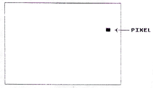
If you'd like to see what a pixel actually looks like in different modes, trying running this program:
10 GRAPHICS 5:? "WHAT GRAPHICS MODE WOULD YOU LIKE? ...
   (ENTER A NUMBER BETWEEN 3 AND 8)"
20 INPUT GM:IF GM<3 OR GM>8 THEN 10
30 GRAPHICS GM
40 COLOR 3
50 PLOT 30,18
60 ? "THIS IS A PIXEL IN GRAPHICS MODE";GM
70 FOR PAUSE=1 TO 1000:NEXT PAUSE
80 GOTO 10
As you may know, all data in random access memory (RAM) is stored in consecutive memory locations called bits. (Eight consecutive bits are called a byte.) Each bit contains either a one or a zero.
A certain part of RAM is used to hold data that will be used to display screen images. Let's call that screen RAM. If a bit in screen RAM is set to one, then the corresponding screen pixel will light up. If a bit is a zero, then the pixel will be turned off.
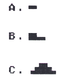
- Suppose a byte (eight bits) contains these values: 00011000. Which of these diagrams correctly shows the screen image that would be displayed by that byte?
|
||||||
ONE- AND TWO-DIMENSIONAL IMAGES
Notice that image "A" above is not yet really a two-dimensional image. It has a horizontal dimension, but no vertical dimension. Actually, it is just a stubby line. Let's make it into a two-dimensional image by turning on some pixels directly beneath it on lines two and three.
Now we have a two-dimensional image. It has height and width. In Ordinary RAM it would be hard to display this image. We would have to do a lot of calculating to figure out which bits in RAM to set to one. Why? Well, RAM is linear; it consists of a series of bytes laid end to end. It is one-dimensional.

On the other hand, screen images are two-dimensional. They have a horizontal and a vertical dimension. Fortunately, the Atari engineers simplified

all this. They arranged for the second byte in PM memory to be displayed directly under the image of the first byte. Similarly, the third byte is displayed directly under the image of the second byte, and so on. This way the data for an image can be stored in consecutive bytes in RAM as illustrated here:
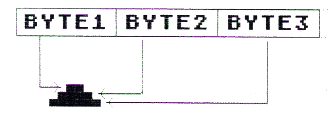
Of course, before you put any data into those consecutive bytes, you need to know exactly what image you want to create. So let's go over the procedure for designing a player image.
DESIGNING A PLAYER IMAGE
First, lay out a grid that is 8 columns wide with as many rows as you like up to 128. For example, you might start with a grid that has 8 columns and 11 rows, like this:
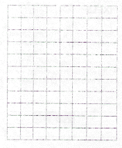
Next, make an image by shading in selected squares on the grid. (Actually, each square on your grid represents a pixel on the display screen.) Here's an example:
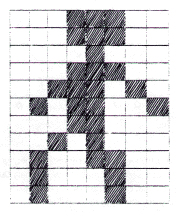
- In this example, how many pixels are lit up to draw the character's neck?
|
||||||
LIGHTING UP PIXELS
The next step is to figure out which bits in memory to set to one so the proper pixels are turned on. This is really quite simple. All we do is convert each row in our grid to a number.
To do that we look at each square in our grid. If the square is shaded in, we write down a "one." If the square is not shaded, we write down a zero. For example, we would convert the first row of our player like this:
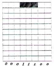
This number--00011100--is called a binary number. Notice that it is composed of just ones and zeros. As you may know, a binary 00011100 is not at all the same as eleven thousand, one hundred (11,100). I'll explain this shortly if you don't understand binary numbers. For now, just remember that we are translating each row of our player into a binary number.
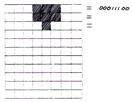
- I did the first row; now you try the second and third. Convert them into binary numbers.
|
||||||
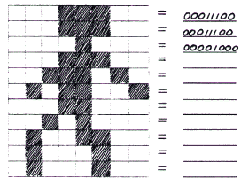
- Now would you like to do the rest?
|
||||||
Now we have all of the binary numbers needed for our player image. But before we can put these values into Atari's memory, we need to convert them into decimal numbers. That's because BASIC was designed for inputing decimal numbers, not binary ones.
If you already know what decimal and binary numbers are and how to convert from binary to decimal, you can skip ahead to "Converting the Image to Decimal Numbers." Otherwise, read on and I'll explain.
Decimal numbers are the kind used by most normal people (You know what I mean--people who aren't assembly language programmers). The word part "dec" means "ten". For example, a decade is a period of ten years. The decimal number system contains ten different number symbols, which are:
0, 1, 2, 3, 4, 5, 6, 7, 8, 9
Similarly, the word part "bi" means "two." For example, bimonthly means "every two months." Binoculars are field glasses designed for use by two eyes. The binary number system uses only two kinds of number symbols: 1's and 0's.
Let's look at some binary numbers. To keep things simple, we'll start out with small binary numbers and put each number symbol in a box.
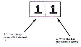
- So a binary 11 represents a decimal 3 since 2 + 1 = 3. What, then, would this binary number represent?

|
||||||
Now let's try a binary number with three number symbols. Again, we'll put each symbol in a box. This time, above each box, we'll show what the box is worth in decimal if it has a "1" in it.
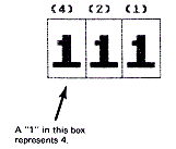
So this binary "111" represents a decimal 7 since 4 + 2 + 1 = 7.
- Got that? Let's see. Give me the decimal equivalent of each of these binary numbers:
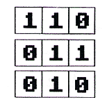
|
||||||
- Let's take away the boxes. What is the decimal equivalent of each of these binary numbers?
a. 101 _____________
b. 010 _____________
c. 001 _____________
d. 111 _____________
|
||||||
Now let's look at an eight-position binary number. We'll put the digits in boxes again to help you visualize the number.

This binary number is equal to 255 since:
128+64+32+16+8+4+2+1=255
- Now, you try one. How much is this in decimal? (Hint: compare this one with the previous binary number.)

|
||||||
- How about this one?
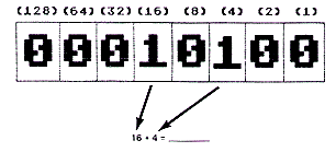
|
||||||
- Try one more.

|
||||||
CONVERTING THE IMAGE TO DECIMAL NUMBERS
Now you're ready to convert your own player image to decimal numbers. Before you do that, however, you may wish to practice on some examples.
- Here's the image we worked on earlier. I've done the first three rows for you. Try the rest if you like:
|
00111100 (4+8+1632) 00011100 (16+8+4) 00001000 (8) 00011100 00111010 01011001 00011000 00101000 01001100 01000100 01000100 |
a. 60 b. 28 c. 8 d. __________ e. __________ f. __________ g. __________ h. __________ i. __________ j. __________ k. __________ |
|
||||||
If you'd like more practice in calculating decimal numbers, you may wish to try this next one. Otherwise, on to the next chapter. I can't wait to show you a new, little-known method for allocating PM memory!
MORE PRACTICE
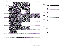
- Give the decimal numbers for creating this shape:
|
||||||
Congratulations. You can now design your own player image and calculate the decimal numbers needed for it. Next, you learn how to reserve memory for your player-missile image data.
Return to Table of Contents | Previous Chapter | Next Chapter

