New RAMS for Old
Steve Olsson
|
If you have an Atari 800 with two 8K memory boards and don't want to upgrade memory by throwing away two expensive modules, you can now upgrade them to two 16Ks for a fraction of the cost of new 16K boards. This upgrade can be done by almost anyone, and does not require extensive hardware knowledge. All it takes is a bit of soldering. The theory is as follows:
The 4116 dynamic memory is a very popular memory chip used by, among others, Apple, TRS80, and Atari. This chip is inexpensive and readily available. It is arranged as a 16K x 1 in a sixteen pin DIP and comes in many different speeds.
The 4116 memory also has a half brother, the 4108. The 4108 is very similar to the 4116, except it is arranged as an 8K x 1. In reality, the 4108 chip is a 4116. Besides the label, there is only one real difference: the 4108 is a 4116 that has a problem. When the chips are manufactured, bad ones are thrown into the reject pile and good ones are shipped. From the reject pile some chips are again sorted and shipped. Chips with the upper half bad and lower half good are sold as 4108-A, and those with the upper half good are sold as 4108-B.
Atari now buys a 4108 chip and accesses only the good half of it on the 8K memory board. If Atari were to install completely good 4116 memory chips and access the entire chip, a 16K memory board would result.
The point is, instead of throwing away the 8K module (which is nearly identical to the 16K module), why not replace the 8K memory chips with 16K memory chips? Several jumper options must be changed, and the 8K memory must be removed from its sockets and replaced with 4116s. The whole process is extremely easy and should take about 30 minutes.
In order to begin the procedure, the first thing to do is order eight 4116 RAMS per board being upgraded from a local supply house. (Care must be taken to choose a reputable supplier. The parts should be guaranteed 100% operational). The cost of the chips ranges from $30 to $60. The chips must have a maximum access time of 200 nS in order to work in the Atari.
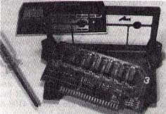
Once the 4116s are in hand, open the top of the Atari and remove an 8K memory module. Remove the two screws that hold the memory module together. Pop off the metal cover and snap open the module along the edge connector. The circuit board now lifts out of the module.
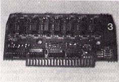
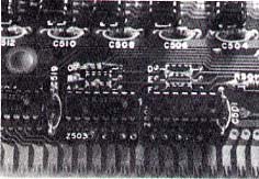
Six jumpers on the front (component side) of the board labeled A. B, C, D, E, F are now exposed. They are actually resistors of very low value but function as jumpers only.
The edge connector is labeled 1-22 on the front and A-Z on the back. (Notice omitted letters G, O, Q, I due to similarities in shape.) The letters connected together by small pieces of etch are: U-T, S-R, and N-P. Also notice the etch from W to Z501 pin 15. All of these small etches must be completely removed with a razor blade or X-acto knife.
Atari was nice enough to add solder holes to all of the connections which must now be soldered. Connectors to be soldered together with small pieces of wire are: Z501 pin 15-U, T-S, P-R, and M-N.
Program 1.
10 GRAPHICS 8
20 SETCOLOR 2,0,0
30 COLOR 1
40 FOR Y=0 TO 159
50 PLOT 0,Y
60 DRAW TO 319,Y
70 NEXT Y
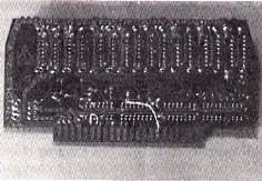
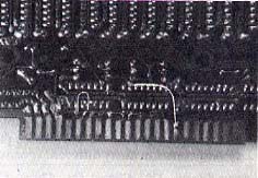
On the front side of the board, jumper C must be installed and all other jumpers removed. On the back of the board a very small solder connection must be made to the connector H as far away from the edge as possible. This wire must be added to hook that signal to jumper D on the side next to the letter (as shown in Figure 4). Make this connection from the back of the board even though the letter is on the front of the board.
The next step is to remove the 8 DIPs labeled C503. C505, C507, C509, C511, C513, C515, and C517 from their sockets and replace them with the 4116s. Replace the board in the module, screw it back together, and the modification is finished!
In order to test the memory, use the following procedures: Insert only the module under test into the Atari then use the ?FRE(0) command to see if the Atari recognizes an increase in memory. If everything looks OK at this point, use graphics 8 mode. Type SETCOLOR 2, 0, 0, which makes the background black. If no spots appear, make the screen white by using Program 1. If, after running this program, there are no holes in the screen pattern, assume the last 8K of memory has no solid errors.
Program 2.
2 X1=14*256
4 X2=65*256
6 X=14
10 POKE 106,X:GRAPHICS 0
20 FOR X=X1 TO X2
30 POKE X,255
40 NEXT X
45 FOR X=X1 to X2
50 IF PEEK (X)<>255 THEN PRINT "ERR-";X
60 POKE X,0
70 NEXT X
80 FOR X=X1 TO X2
90 IF PEEK (X)<>0 THEN PRINT "ERR-";X
100 NEXT X
After this test run Program 2 to check more of the memory. This program checks each memory location (without interfering with Basic) and reports failures to the screen. A few failures could mean there are some bad chips; many failures probably mean the module was wired wrong or the chips are very bad. The failure will probably have to be determined from the failure report generated by Program 2, which reports the address of failure. PEEK and POKE must be used to determine which bit is bad. Program 2 cannot check the first 5K of memory in the module, but if the program runs without strange things happening it is probably all right.
If a memory board is known to be good, place it in slot 1 in memory. If the total memory is now 24K, change lines in Program 2 to:
2 X1 = 32*256
4 X2 = 96*256
6 X  = 32
If the total memory is 32K, change lines in Program 2 to:
2 X1 = 64*256
4 X2 = 128*256
6 X  = 64
The program can now be run. This will completely test the new memory module, and will take about 10-14 minutes to run. If you had only one 8K module that is now a sixteen, you will have to hope the first 5K of memory is good until you get more. The first 5K is impossible to test with only one module.
If your computer passes all these tests, the memory in your Atari has just been doubled. If you have any trouble that is not understandable and have rechecked the procedure to verify that it was done right, you probably have bad RAMs.
This simple procedure will, I hope, save many people lots of money, allowing them to operate with a disk drive and have plenty of memory left for the other programs.
|
Photo 1. The open 8K module. Photo 2. The component side of the memory board. Photo 3. Close up of the jumpers A-F. Photo 4. Correctly installed 16K jumpers on back of hoard. Photo 5. The etch side of the completed mod. |
|
|
| Photo 1. | Photo 2. | |
|
|
|
| Photo 3. | Photo 4. | Photo 5. |
Steve Olsson, 3392 Clipper Dr., Chino, CA 91710.
Table of Contents
Previous Section: Joytricks
Next Section: K-DOS